


7
Cisco uBR7200 Series Universal Broadband Router AC Power Supply Replacement Instructions
78-4848-06
Installation Prerequisites
Preventing Electrostatic Discharge Damage
Electrostatic discharge (ESD) damages equipment and impairs electrical circuitry. ESD occurs when
printed circuit boards are improperly handled and results in complete or intermittent failures.
The I/O controller, network processing engine, cable modem cards, and port adapters consist of a printed
circuit board that is fixed in a metal carrier. Electromagnetic interference (EMI) shielding, connectors,
and handle are integral components of the carrier. Handle the I/O controller, network processing engine,
cable modem cards, and port adapters by their carrier edges and handle only; never touch the printed
circuit board components or connector pins.
Although the metal carrier helps to protect the printed circuit boards from ESD, wear a preventive
antistatic strap whenever handling the network processing engine, I/O controller, cable modem cards, or
port adapters. Ensure that the strap makes good skin contact, and connect the strap’s clip to an unpainted
chassis surface to safely channel unwanted ESD voltages to ground. If no wrist strap is available, ground
yourself by touching the unpainted metal part of the chassis.
Caution Make sure to tighten the captive installation screws on the network processing engine, cable modem
cards, and I/O controller (use a number 2 Phillips screwdriver). These screws prevent accidental
removal, provide proper grounding for the router, and help to ensure that the network processing engine,
cable modem cards, and I/O controller are properly seated in the router midplane.
Following are guidelines for preventing ESD damage:
• Always use an ESD wrist strap or ankle strap when installing or replacing the I/O controller, network
processing engine, or port adapters. Ensure that the ESD strap makes contact with your skin.
• Handle the I/O controller, network processing engine, or port adapters by their metal carrier edges
and handles only; avoid touching the printed circuit board components or any connector pins.
• When removing the I/O controller, network processing engine, or port adapters, place them on an
antistatic surface with the printed circuit board components facing upward, or in a static shielding
bag. If you are returning an I/O controller, network processing engine, or port adapter to the factory,
immediately place it in a static shielding bag.
Caution Periodically check the resistance value of the antistatic strap. The measurement should be within the
range of 1 and 10 megohms (Mohms).
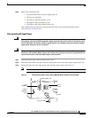
Ensuring Easy Access to the Router
If your Cisco uBR7200 series router is installed in a standard 19-inch-wide, four-post equipment rack or
telco-type equipment rack, cables from other equipment in the rack might obstruct access to the rear of
the router. Also, rack power strips or other permanent fixtures might obstruct access to the router. Review
the following guidelines to ensure easy access to the rear of the router when it is installed in a rack. If
the router is not installed in a rack, or if you already have clear access to the rear of the router, proceed
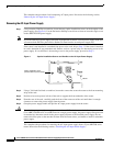
to the “Removing and Replacing an AC-Input Power Supply” section on page 8.
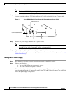
Use the following guidelines to ensure easy access to the rear of the router when it is installed in a rack:
• Ensure that you have at least three to four feet of working space at the rear of the router.
• If cables from other equipment in the rack fall in front of the rear end of the router, carefully gather
the cables (using care not to strain them) and use cable ties to anchor them away from the rear of the
router.