


16
AC Power Supplies
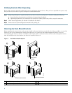
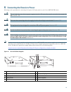
Step 1 At the rear of the router, ensure that the power switch on the power supply is in the OFF (0) position.
Step 2 Slide the cable-retention clip to the left, away from the AC receptacle, and plug in the power cable.
Step 3 Secure the cable in the power supply AC receptacle by sliding the cable-retention clip to the right until it fits around
the connector. The cable-retention clip provides strain relief for the AC power cable.
Tip For additional AC power cable strain relief, secure the cable to the power supply handle by inserting a nylon cable tie
through the hole in the handle and around the cable.
Step 4 Plug the AC power supply cable into the AC power source.
Step 5 Repeat Step 1 through Step 4 for the second power supply (if present).
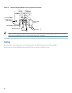
Figure 11 Connecting AC-Input Power
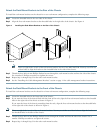
DC Power Supplies
Warning
Before performing any of the following procedures, ensure that power is removed from the DC circuit.
Statement
1003
Warning
When installing or replacing the unit, the ground connection must always be made first and disconnected last.
Statement 1046
Warning
A readily accessible two-poled disconnect device must be incorporated in the fixed wiring.
Statement 1022
Note The color-coding of the DC-input power supply leads depends on the color-coding of the DC power source at your site.
Typically, green or green/yellow is used for ground, black is used for +48V (return), and red or white is used for –48V.
Make certain that the lead color-coding you choose for the DC-input power supply matches lead color-coding used at
the DC power source.
103562
Power
switch
Handle
AC power cable
Power
receptacle
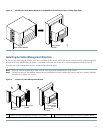
Captive
installation
screw