


7
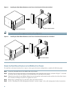
4 Installing the Chassis
Rack-Mount Installation Guidelines
• Allow sufficient clearance around the rack for maintenance.You need 36 in. (91.44 cm) of clearance to remove and replace
system components.
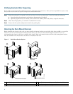
• If the Cisco uBR7246VXR chassis is the only unit in a rack, mount the chassis at the bottom of the rack. Use the rack-mount
kit that comes with the chassis.
• Always place the heavier equipment in the lower half of the rack.
• If the rack is provided with stabilizing devices, install the stabilizers before mounting the chassis.
• Make sure that an open or relay racks are bolted to the floor.
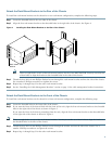
• When mounting the chassis in 4-post or relay racks, use all the screws and brackets that are provided.
• For 23-inch racks, order optional mounting brackets from third-party vendors.
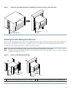
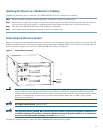
Workbench and Tabletop Installation Guidelines
When installing the router on a workbench or tabletop, check the following:
• There is at least 3 inches (7.72 cm) of clearance at the inlet and exhaust vents (the right and left sides of the router).
• There is approximately 23.25 inches (59.06 cm) of clearance at the front, and 19 inches (48.3 cm) at the back of the router
for installing and replacing field-replaceable units (FRUs), or accessing network cables or equipment.
• There is adequate ventilation (it is being installed in an enclosed cabinet where ventilation is adequate).
• Blank panels are installed in any slot that does not have a component.
• The cable-management bracket and four M4 x 6-mm Phillips panhead screws are set aside (if required).
Warning
Do not stack the chassis on any other equipment. If the chassis falls, it can cause severe bodily injury and
equipment damage.
Statement 48
Installation Tools and Equipment
The tools and equipment listed below are recommended as the minimum necessary to install the Cisco uBR7246VXR router.
Other equipment may include test equipment to check electronic and optical signal levels, power levels, and communications
links.
• Rack-mounting kit (includes brackets and screws)
• Number 2 Phillips screwdriver
• 3/16-inch flat-blade screwdriver
• 1/4-inch flat-blade screwdriver
• 8-mm wrench or nut driver, or adjustable wrench
• 7-mm wrench or nut driver, or adjustable wrench
• DC-input cable—14 AWG (2.08 mm
2
) cable with a minimum of three conductors rated for at least 140° F (60
° C)
• AC-input cable—18 AWG cable with a 3-lead IEC-320 receptacle on the power supply end, and a country-dependent plug
on the other end
• Antistatic mat or antistatic foam and electrostatic discharge (ESD) grounding strap or the disposable ESD strap
• Wire stripper and crimping tool. (The accessory kit comes with ground lugs and M5 screws with captive, locking washers.)
• Wire—6 AWG (16 mm), provided by the customer