


17
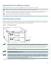
Tools
• 8-mm wrench or nut driver, or adjustable wrench (for connecting a grounding lug to a DC-input power supply only)
• 7-mm wrench or nut driver, or adjustable wrench (for connecting the DC-input power lead strain-relief cover to a DC-input
power supply only)
• 14 AWG (2.08 mm
2
) cable with a minimum of three conductors rated for at least 140
° F (60° C) (for DC-input power
supply installations only)
• Standard wire stripper
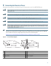
Step 1 Ensure that the –48V and +48V leads are disconnected from the power source.
Step 2 At the rear of the router, check that the power switch on the power supply is in the OFF (0) position.
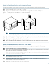
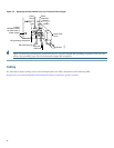
Step 3 Connect the two-hole grounding lug on the ground wire to the M5 grounding receptacles with the two M5 nuts. Tighten
the nuts using an 8-mm wrench or nut driver (or adjustable wrench). See Figure 12.
Step 4 Using a wire stripper, strip approximately 0.55 inch (14 mm) from the –48V and +48V leads.
Step 5 Insert the stripped end of the +48V lead all the way into the +48V lead receptacle and tighten the receptacle screw using
a 3/16-inch flat-blade screwdriver. Repeat for the –48V lead.
Step 6 Make sure that the entire stripped end of each lead is inserted all the way into its receptacle. If any exposed wire at the
stripped end of a lead is visible after inserting the lead into its receptacle, remove the lead from the receptacle, use the
wire stripper to cut the stripped end of the lead, and repeat Step 4 and Step 5.
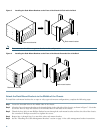
Step 7 After tightening the receptacle screws and nuts for the ground, +48V, and –48V DC-input leads, run the +48V and –48V
leads between the two strain-relief studs on the power supply faceplate. (See Figure 12 on page 18.)
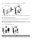
Step 8 Install the strain-relief cover over the +48V and –48V leads and secure the cover to the strain-relief studs using the two
M4 nuts with a 7-mm wrench or nut driver (or adjustable wrench). (See Figure 12.)
Step 9 Connect the ground wire, +48V lead, and –48V lead to the power source.
Caution Each DC-input power supply has an electrical current rating of 14 A, 700 VA. Use a minimum of 14 AWG
(2.08 mm
2
) wire for the input to each DC-input power supply. The power input must be protected by a 20 A circuit
breaker or fuse that is in compliance with your local electric regulations.
Warning
The illustration shows the DC power supply terminal block. Wire the DC power supply using the appropriate wire
terminations at the wiring end, as illustrated. The proper wiring sequence is ground to ground, positive to positive
(line to L), and negative to negative (neutral to N). Note that the ground wire should always be connected first and
disconnected last.
Statement 61