


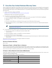

4
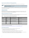
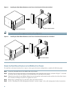
Figure 1 Front and Rear Chassis Views
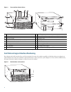
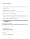
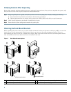
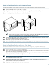
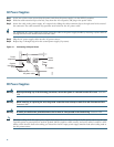
Card Slot and Logical Interface Numbering
Port adapter and cable interface line card slots maintain the same slot number regardless of whether other port adapters or
cable interface line cards are installed or removed. However, when you move a port adapter or a line card to a different slot,
the logical interface number changes to reflect the new slot number.
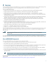
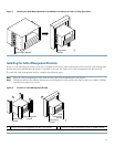
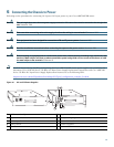
Figure 2 Slot Numbers and Locations
1
Internal fans
9
Auxiliary port
2
Clock card
10
Optional Fast Ethernet port (M11 and RJ-45 receptacles)
3
Fan tray handle
11
PCMCIA slots
4
Captive installation screws (line cards)
12
AC plug
1
1. AC power supplies are shown in this illustration. DC power supplies are also available.
5
Cable interface line cards
13
Power switch
6
Port adapters
14
Power supply handle
7
I/O controller
15
AC-input power supply
8
Console port
16
Network processing engine (NPE)
103555
US2
US4
US5
US6
US7
DS0-RF
DS1-RF
u
BR - M
C28U
US1
US0
US3
US2
US4
US5
US6
US7
DS0-RF
DS1-RF
u
BR - M
C28U
US1
US0
US3
US2
US4
US5
US6
US7
DS0-RF
DS1-RF
uBR - M
C28U
US1
US0
US3
US2
US4
US5
US6
US7
DS0-RF
DS1-RF
uBR
- M
C28U
US1
US0
US3
11
109
12
13
3
1
2
4
5
6
7
8
103563
US2
US4
US5
US6
US7
DS0-RF
DS1-RF
uB
R
- M
C
28U
US1
US0
US3
US2
US4
US5
US6
US7
DS0-RF
DS1-RF
uBR
- M
C
28U
US1
US0
US3
US2
US4
US5
US6
US7
DS0-RF
DS1-RF
uBR
- M
C
28U
US1
US0
US3
US2
US4
US5
US6
US7
DS0-RF
DS1-RF
uBR
- M
C
28U
US1
US0
US3
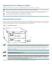
Slot 3
Slot 4