


18
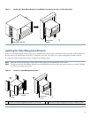
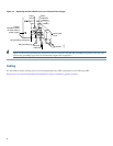
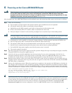
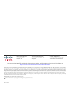
Figure 12 Replacing the Strain-Relief Cover on a DC-Input Power Supply
Tip Figure 12 shows the grounding lug connected to the two vertically aligned M5 grounding receptacles. You may also
connect the grounding lug to the two horizontally aligned M5 receptacles.
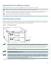
Cabling
For information about cabling, refer to the field-replaceable unit (FRU) documents at the following URL:
http://www.cisco.com/en/US/products/hw/cable/ps2217/prod_installation_guides_list.html
103573
Power
switch
Power
receptacle
Strain-relief
cover
M4 nuts
M5 grounding lug
Captive
installation screw
(on both sides of
power supply)
M5 grounding receptacles
+ 48V lead
– 48V lead