


CBM1000 Service Manual
–
9
–
CITIZEN
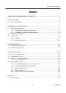
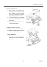
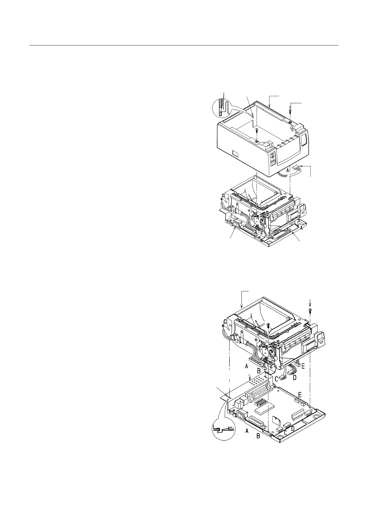
3.
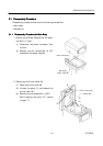
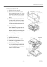
Removing the Top Cover SA
(1) Remove the printer cover SA.
(2) Remove the two screws M3 × 6 (ST).
While unhooking the part “B” of the
frame from the top cover SA, lift the top
cover. At this time, avoid the power
switch.
(3) Unhook the operation panel cable from
the cable holder, disconnect the opera-
tion panel connector from the control
PCB assy, and remove the top cover SA.
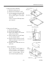
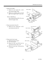
Note on reassembling:
When reassembling the top cover SA,
be sure that the part “B” of the frame is
securely inserted into the square hole
at the back of the top cover SA as
shown in the figure.
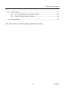
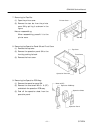
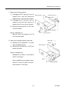
4. Removing the Mechanism Unit
(1) Remove the top cover SA.
(2) Remove the two screws M3 × 6 (ST).
(3) Disconnect the five connectors “A to E”
from the control PCB assy.
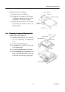
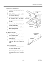
(4) Lift the front part of the mechanism
unit a little and remove the mechanism
unit by disengaging it from two square
holes on the bottom chassis.
Operation Panel
Connector
M3
×
6 (ST)
Top Cover SA
Power Switch
Cable Holder
Mechanism Unit
M3
×
6 (ST)
Bottom Chassis
Square Hole
Square Hole
B