


Compaq Presario Series Maintenance and Service Guide
United States December 9, 2002
Presario 305 Model
Before You Begin Specifications Parts Catalog
Removal Sequence Troubleshooting Battery Operations
Product Description Pin Assignments
Index
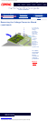
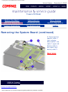
Removing the System Board
Removal
Sequence
Serial Number
Location
Preparing for
Disassembly
Electrostatic
Discharge
Service
Considerations
Cables and
Connectors
Multi-media
Expansion
Unit
Battery Pack
Hard Drive
Modem Card
RTC Battery
Keyboard
Memory Board
Switch Cover
Display Panel
Deck
Voltage
Converter
Board
Modem
Connector
Board
PC Card
PC Card
Assembly
System
Board
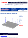
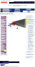
NOTE:
There are
different
sized screws
securing the
system
board to the
base
enclosure.
Make note
of the
location of
these
screws.
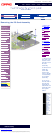
Also, when
the system
board is
removed,
components
of the base
enclosure
tend to fall
loose. Note
the location
and
orientation
of all base
enclosure
components.
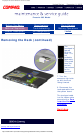
1. Remove the
RTC battery.
2.
Remove the
keyboard.
3.
Remove the
switch cover.
4.
Remove the
display.
5.
Remove the
deck.
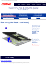
6.
Remove the
modem
connector
board.
7.
Remove the
PC card
assembly.
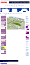
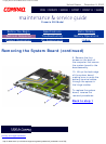
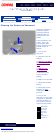
8. Remove the
four screws that
secure the
system board to
the base
assembly from
the top.
Next Step
privacy and legal statement
http://h18000.www1.hp.com/athome/support/msgs/305/sysbrd1.html [12/9/2002 2:19:35 PM]