


Index–2 Maintenance and Service Guide
Index
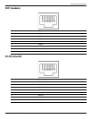
RJ-11 jack 9–3
RJ-45 jack
9–3
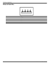
USB port
9–4
connectors, service considerations
4–1
creating a backup
8–2
D
device configurations 5–5
Diagnostics menu
5–4
Disk Sanitizer
5–4, 5–9
display assembly
removal
4–25
spare part numbers
3–3, 3–17, 3–19, 4–25
display bezel
illustrated
3–9
removal
4–28
spare part numbers
3–9, 3–17, 4–28
Display Cable Kit
illustrated
3–9
spare part number
3–9, 3–18
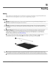
display components
illustrated
2–1
recycling
11–1
spare part numbers
3–9
display enclosure
illustrated
3–9
removal
4–28
spare part number
3–9, 3–17
display hinge
illustrated
3–9
removal
4–29, 4–30
spare part number
3–9, 3–18, 4–30
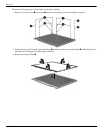
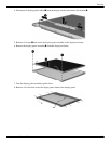
display inverter, removal
11–3
display panel cable
illustrated
3–9
removal
4–30
spare part number
4–30
display panel, product description
1–2
display switch
2–3
DriveLock password
5–4, 5–9
DriveLock, automatic
5–4
drives, boot order
5–5, 5–10
DVD±RW and CD-RW SuperMulti Double-Layer
Drive
precautions
4–2
removal
4–18
spare part numbers
3–8, 3–11, 3–17, 4–18
specifications
6–4
DVD-ROM Drive
precautions
4–2
removal
4–18
spare part numbers
3–8, 3–11, 3–17, 3–20, 4–18
specifications
6–5
E
electrostatic discharge 4–2
equipment guidelines
4–4
error log
5–4
esc key 2–4
Ethernet product description
1–4
Execution Disable
5–10
ExpressCard slot
2–9
ExpressCard slot bezel, illustrated
3–12
external media card product description
1–4
external monitor port
connector pinout
9–2
location
2–9
F
f11 recovery 8–4
fan
removal
4–38
spare part number
3–5, 3–18, 4–38
feet
locations
4–6
spare part number
4–6
File menu
5–3, 5–8
fn key 2–4
front components
2–7
function keys
2–4
G
graphics product description 1–2
grounding equipment and methods
4–2
H
hard disk test 5–4
hard drive
precautions
4–2
product description
1–3
removal
4–8
spare part numbers
3–8, 3–11, 3–16, 3–17, 3–19,
4–8
specifications
6–3
hard drive bay
2–10
hard drive bracket, removal
4–11
hard drive cover
illustrated
3–12
removal
4–9
hard drive recovery
8–4
hard drive test
5–9
headphone jack
connector pinout
9–1
location
2–2, 2–7
heat sink
removal
4–44
spare part numbers
3–5, 3–18, 4–44