


4–36 Maintenance and Service Guide
Removal and replacement procedures
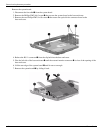
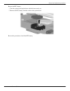
Remove the system board:
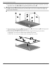
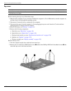
1. Disconnect the fan cable 1 from the system board.
2. Remove the Phillips PM2.5×4.0 screw 2 that secures the system board to the base enclosure.
3. Remove the two Phillips PM2.5×4.0 screws 3 that secure the optical drive connector board to the
base enclosure.
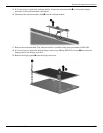
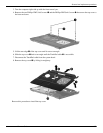
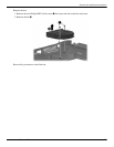
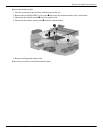
4. Release the RJ-11 connector 1 from the clip built into the base enclosure.
5. Flex the left side of the base enclosure 2 until the external monitor connector 3 is clear of the opening of the
base enclosure.
6. Lift the rear edge of the system board 4 until it rests at an angle.
7. Remove the system board 5 by sliding it back.