


Removal and replacement procedures
Maintenance and Service Guide 4–27
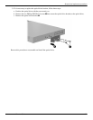
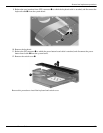
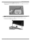
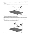
8. Disconnect the webcam module cable 1 from the system board.
9. Remove the wireless antenna cables 2 and the microphone cable from the clips 3 and routing channel built
into the top cover.
Ä
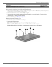
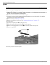
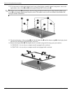
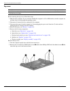
CAUTION: Support the display assembly when removing the following screws. Failure to support the display
assembly can result in damage to the display assembly and other computer components.
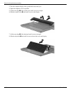
10. Remove the four Phillips PM2.5×6.0 screws 1 that secure the display assembly to the computer.
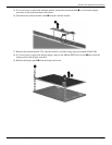
11. Lift the display assembly 2 straight up and remove it.