


4–28 Maintenance and Service Guide
Removal and replacement procedures
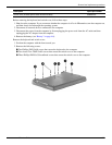
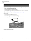
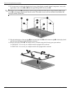
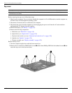
12. If it is necessary to replace the display bezel or any of the display assembly internal components, remove the
eight rubber screw covers 1 and 2 and the eight Phillips PM2.5×6.0 screws 3.
✎
The rubber screw covers 1 on the display bezel top edge and bottom inside edge are larger than the rubber screw
covers 2 on the display bezel bottom outside corners. The rubber screw covers are included in the Rubber Kit,
spare part number 538448-001.
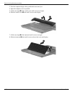
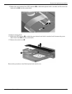
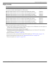
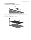
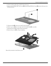
13. Flex the inside edges of the top edge 1, the left and right sides 2, and the bottom edge 3 of the display bezel
until the bezel disengages from the display enclosure.
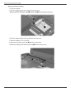
14. Remove the display bezel 4. The display bezel is available using the following spare part numbers:
❏ 538428-001—for use only on computer models equipped with a webcam
❏ 538427-001—for use only on computer models not equipped with a webcam