


Connector Pin Assignments
Maintenance and Service Guide A–3
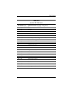
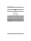
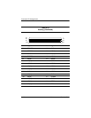
Table A-5
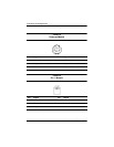
RJ-45 Network Interface
Pin Signal Pin Signal
1 Transmit + 5 Unused
2 Transmit - 6 Receive -
3 Receive + 7 Unused
4 Unused 8 Unused
6
5
4
3
2
1
7
8
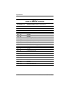
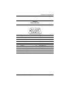
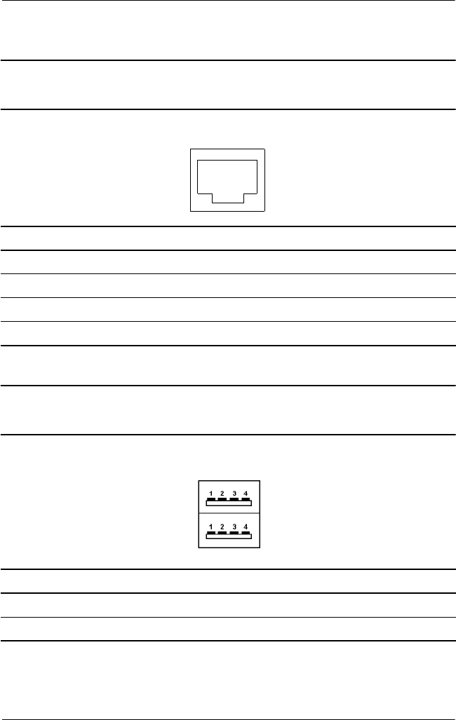
Table A-6
Universal Serial Bus
Pin Signal Pin Signal
1 +5 VDC 3 Data +
2 Data - 4 Ground