


5–18 Maintenance and Service Guide
Removal and Replacement Procedures
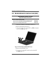
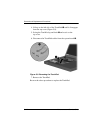
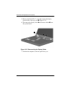
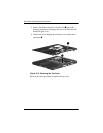
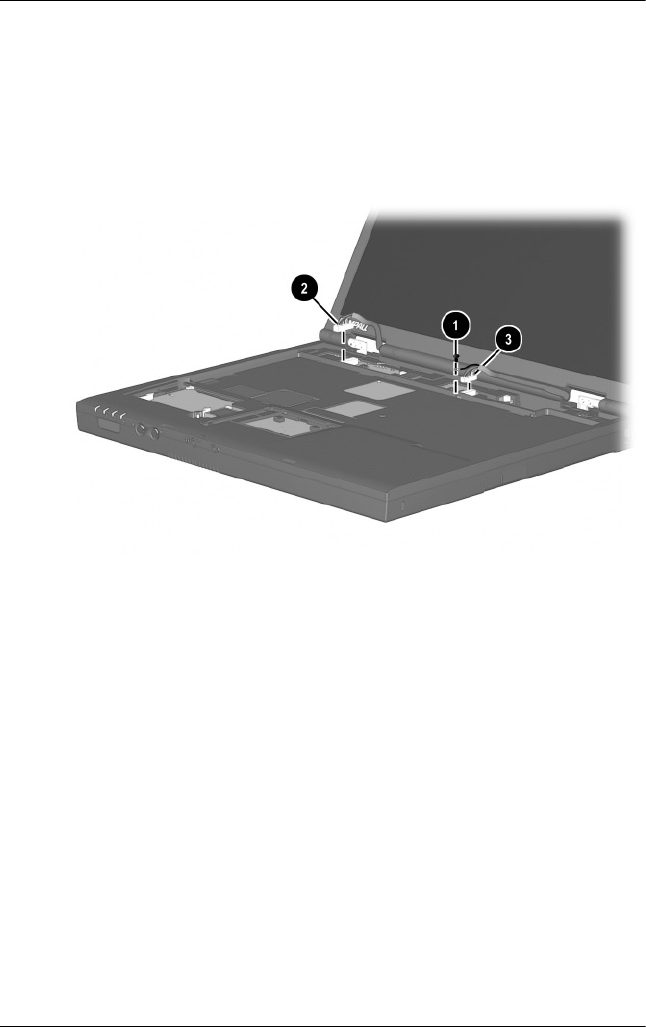
5. Remove the black M2 × 7 screw that secures the display
ground cable to the top cover 1 (Figure 5-12).
6. Disconnect the display video 2 and inverter cables 3 from
the system board.
Figure 5-12. Disconnecting the Display Cables
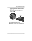
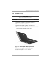
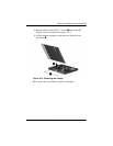
7. Position the computer so the rear panel faces you.