


Removal and Replacement Procedures
Maintenance and Service Guide 5–21
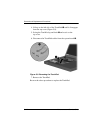
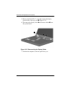
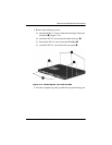
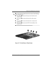
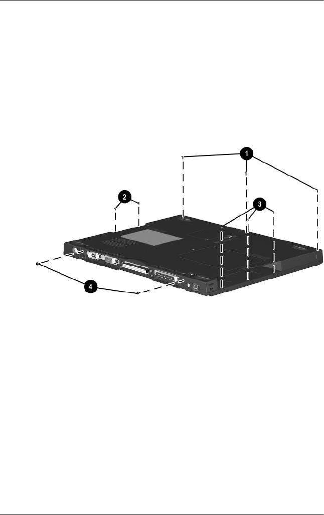
3. Remove the following screws:
❏ three black M2 × 7 screws from the front edge of the base
enclosure 1 (Figure 5-14)
❏ two black M2 × 5 screws from the hard drive bay 2
❏ three black M2 × 5 screws from the MultiBay 3
❏ two black M2 × 5 screws from the rear panel 4
Figure 5-14. Removing the Top Cover Screws
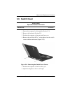
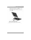
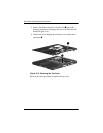
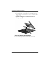
4. Turn the computer top side up with the rear panel facing you.