


Removal and Replacement Procedures
Maintenance and Service Guide 5–3
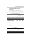
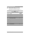
5.2 Disassembly Sequence Chart
Use the chart below to determine the section number to be
referenced when removing computer components.
Table 5-1
Disassembly Sequence Chart
Section Description
# of Screws
Removed
5.3 Preparing the computer for disassembly 0
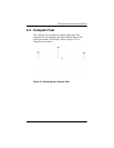
5.4 Computer feet 0
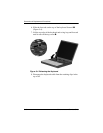
5.5 Keyboard 1
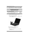
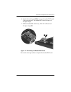
5.6 Modem/Network Interface Card (NIC) 0
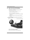
5.7 Real Time Clock (RTC) battery 0
5.8 TouchPad and Touch button 0
5.9 Switch cover 2
5.10 Display 3
5.11 Top cover 10
5.12 System board 5
5.13 Fan 2
5.14 DC-DC converter board 0
5.15 Modem cable 0