


Crestron iServer™ Network Audio Server Crestron CEN-ISERVER
Connectors, Controls & Indicators (Continued)
#
CONNECTORS
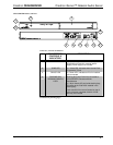
1
,
CONTROLS &
INDICATORS
DESCRIPTION
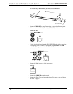
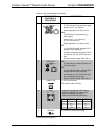
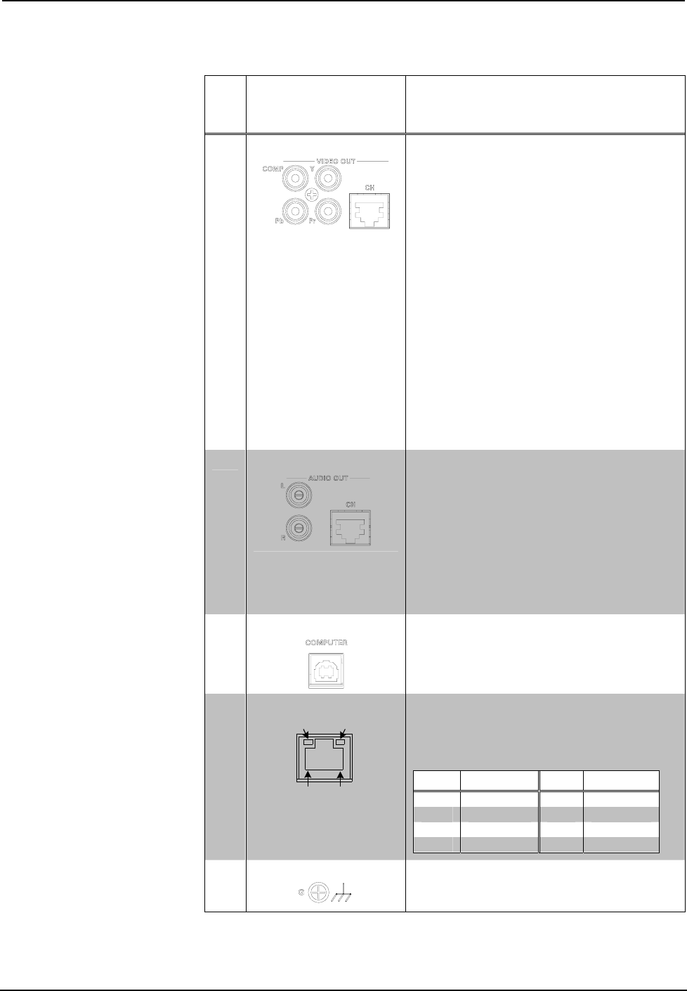
5 VIDEO OUT
Composite:
(1) RCA female; Composite video output;
Output Level: 1 V
p-p
nominal;
Output Impedance: 75 ohms nominal
YP
b
P
r
:
(3) RCA female; Component (YP
b
P
r
)
video output;
Output Level: 1 V
p-p
nominal (Y),
0.7 V
p-p
nominal (P
b
P
r
);
Output Impedance: 75 ohms nominal
CH
2
:
(1) 8-pin RJ-45 female, shielded; CAT5
balanced video output port;
Formats: Composite, component (YP
b
P
r
);
Connects to any “CH” CAT5 video input
port;
Maximum Cable Length: 500 ft (152 m)
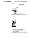
6 AUDIO OUT
L-R:
(2) RCA female; Unbalanced stereo line-
level audio output
CH
3
:
(1) 8-wire RJ-45 female, shielded; CAT5
balanced stereo audio output port;
Connects to any “CH” CAT5 audio input
port or bidirectional audio port;
Maximum Cable Length: 500 ft (152 m)
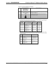
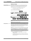
7 COMPUTER
(1) USB Type B female;
USB 2.0 port (cable included)
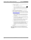
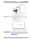
8
LAN
GREEN
LED
YELLOW
LED
PIN 8
PIN 1
(1) 8-wire RJ-45 with two LED indicators;
10BASE-T/100BASE-TX Ethernet port;
Green LED indicates link status;
Yellow LED indicates Ethernet activity.
PIN SIGNAL PIN SIGNAL
1 TX + 5 N/C
2 TX - 6 RC -
3 RC+ 7 N/C
4 N/C 8 N/C
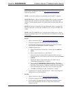
9
GROUND
(1) 6-32 screw, chassis ground lug.
(Continued on following page)
6 • Crestron iServer™ Network Audio Server: CEN-ISERVER Operations Guide – DOC. 6759B