Crestron CEN-ISERVER Crestron iServer™ Network Audio Server
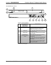
Connectors, Controls & Indicators (Continued)
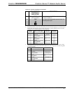
#
CONNECTORS
1
,
CONTROLS &
INDICATORS
DESCRIPTION
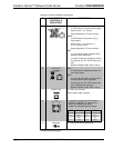
10
SETUP
(LED and button)
Used to setup unit’s IP ID in conjunction with
Crestron Toolbox™.
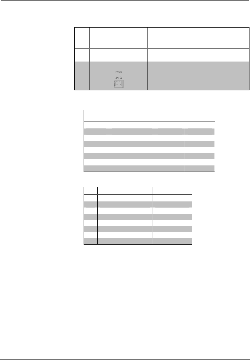
11 PWR
(1) 2-pin 3.5mm detachable terminal block; 24
Volt DC power input
1. An interface connector for the PWR port is provided with the unit.
2. This eight-pin RJ-45 port provides connectivity to a device with a CH input port or a Crestron device
with a CAT5 video input. This port provides component or composite balanced output over CAT5
wiring. Refer to the following table for connector pinouts.
RJ-45 PIN
NUMBER
WIRE COLORS (568B) COMPOSITE COMPONENT
1 WHITE/ORANGE + Composite + Y
2 ORANGE - Composite - Y
3 WHITE/GREEN N/A + P
b
4 BLUE N/A + P
r
5 WHITE/BLUE N/A - P
r
6 GREEN N/A - P
b
7 WHITE/BROWN N/A N/A
8 BROWN N/A N/A
3. This eight-pin RJ-45 port provides connectivity to the CNX-BIPAD or or a Crestron device with a
CAT5 audio input. This port provides stereo output over CAT5 wiring. Refer to the following table
for connector pinouts.
PIN WIRE COLORS (568B) AUDIO I/O
1 WHITE/ORANGE + Audio Left Out
2 ORANGE - Audio Left Out
3 WHITE/GREEN + Audio Right Out
4 BLUE N/A
5 WHITE/BLUE N/A
6 GREEN - Audio Right Out
7 WHITE/BROWN N/A
8 BROWN N/A
Operations Guide – DOC. 6759B Crestron iServer™ Network Audio Server: CEN-ISERVER • 7


