


Multimedia Presentation System 300 Crestron MPS-300
Connectors, Controls & Indicators (Continued)
#
CONNECTORS
1
,
CONTROLS &
INDICATORS
DESCRIPTION
8
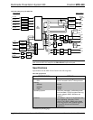
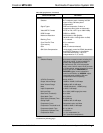
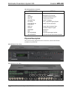
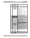
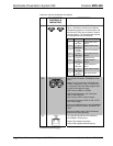
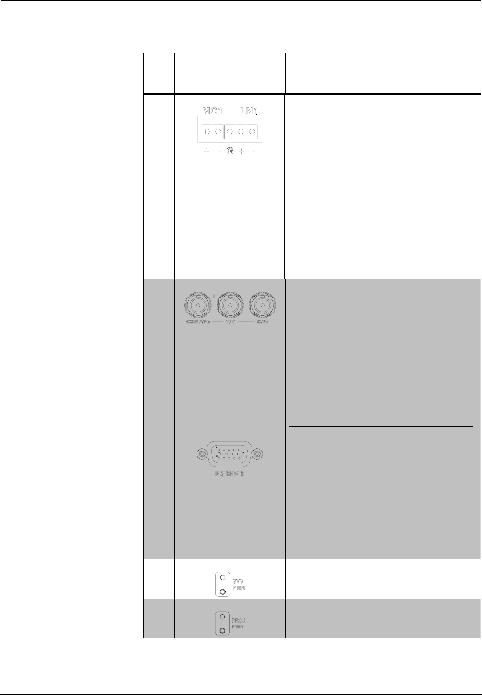
MC/LN 1 – 2
(2) 5-pin 3.5 mm detachable terminal blocks;
Comprises (2) Balanced microphone/line
inputs;
Balanced Mic Input Level: -52 to -12 dBV,
240 mV
rms
maximum;
Balanced Line Input Level: -28 to +11 dBV;
3.7 V
rms
maximum;
Unbalanced Line Input Level: -34 to +5 dBV;
1.85 V
rms
maximum;
Mic Input Impedance: 3.9k ohms, accepts 60
to 600 ohm source;
Line Input Impedance: 19k ohms (balanced),
9.5k ohms (unbalanced);
Phantom Power: 10 mA (total) @ 48 Volts DC,
software enabled to both mic inputs
9
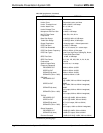
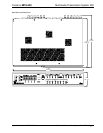
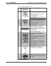
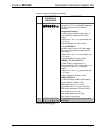
VIDEO INPUTS 1 - 2
RGBHV INPUTS 3 - 5
(2) sets of (3) BNC female video inputs, each
set configurable as:
• Component/HDTV (YP
b
P
r
) video
input, or
• S-video (Y/C) input, or
• Composite input
Input Level: 1 V
p-p
nominal;
Input Impedance: 75 ohms nominal;
DC Offset: Insensitive to DC offset
(AC coupled);
Video signal sensing on COMP/P
b
or Y/Y
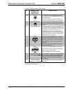
(3) DB15HD female, RGBHV (VGA) inputs;
Format: RGBHV or RGBS;
RGB Input Level: 1 V
p-p
nominal;
RGB Input Impedance: 75 ohms nominal;
Sync Input Level: 2 to 5 V
p-p
;
Sync Input Impedance: 75, 500, or 1k ohms
individually selectable for H and V via bottom
panel DIP switch;
Video signal sensing on “H-SYNC”;
Defeatable DDC pull-up resistors
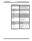
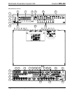
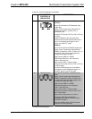
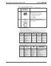
10
SYSTEM POWER
(1) pushbutton and green LED, controls
system power
11
PROJECTOR POWER
(1) pushbutton and green LED, controls
display device power
(Continued on following page)
14 • Multimedia Presentation System 300: MPS-300 Operations Guide – DOC. 6529B