


Crestron MPS-300 Multimedia Presentation System 300
Connectors, Controls & Indicators (Continued)
#
CONNECTORS
1
,
CONTROLS &
INDICATORS
DESCRIPTION
12
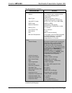
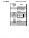
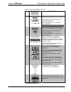
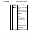
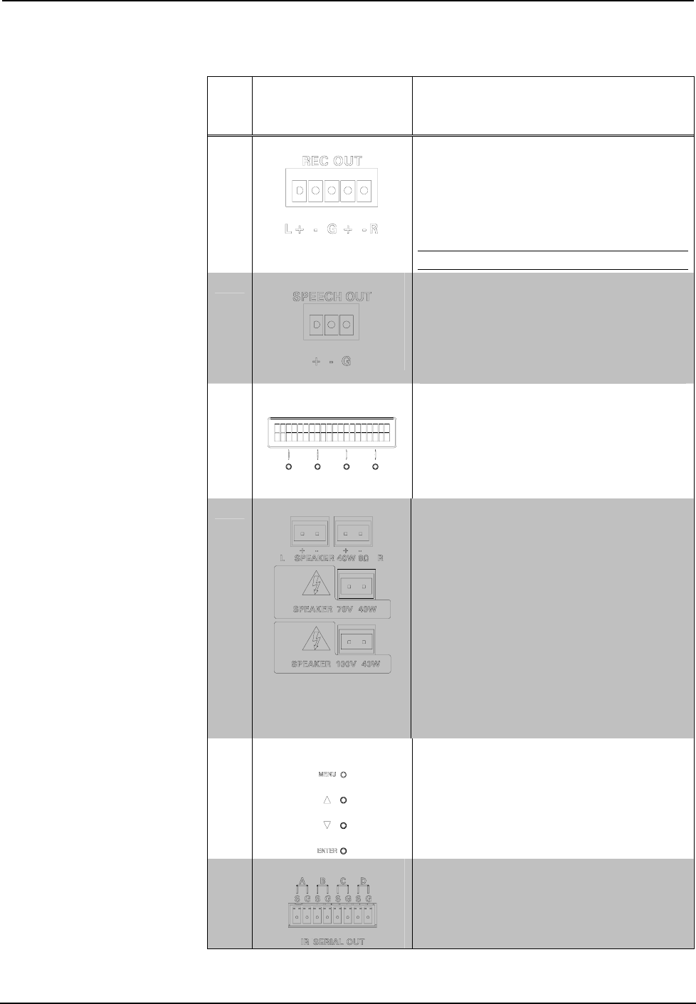
REC OUT
(1) 5-pin 3.5 mm detachable terminal block;
Balanced/unbalanced, stereo line-level output;
Output Impedance: 200 ohms balanced,
100 ohms unbalanced;
Maximum Output Level: 4 V
rms
balanced,
2 V
rms
unbalanced
NOTE: Does not include relay mute.
13
SPEECH OUT
(1) 3-pin 3.5 mm detachable terminal block;
Balanced/unbalanced mono line-level output;
Output Impedance: 200 ohms balanced,
100 ohms unbalanced;
Maximum Output Level: 4 V
rms
balanced,
2 V
rms
unbalanced
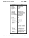
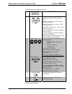
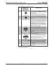
14
LCD DISPLAY AND
SOFT BUTTONS
Green LCD alphanumeric, adjustable
backlight; 2 lines x 20 characters per line;
Displays input/outputs by name, volume level
bargraph, setup menus, time/date, and other
system information
(4) pushbuttons for activation of LCD driven
functions and passcode entry
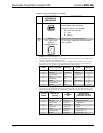
15
SPEAKER OUTPUTS
(1 or 2) 2-pin 5 mm detachable terminal
blocks; Speaker-level audio outputs
(MPS-300);
(1) 2-pin 5 mm detachable terminal blocks;
Speaker-level audio outputs (MPS-300-70V
and MPS-300-100V)
Wire Size: Connector accepts 12 AWG
maximum
Output Power (MPS-300): 20W RMS per
channel stereo into 8 ohms, 4 ohms tolerant;
Output Power (MPS-300-70V): 40W RMS
mono at 70 Volts;
Output Power (MPS-300-100V): 40W RMS
mono at 100 Volts
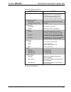
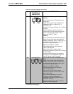
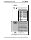
16
NAVIGATION
BUTTONS
(4) Pushbuttons for navigating the
configuration menus of the MPS-300
17
IR/SERIAL OUT
(4) 2-pin 3.5 mm detachable terminal blocks,
IR/Serial output ports; IR output up to 1.2 MHz;
One-way serial TTL/RS-232 (0-5 Volts)
2
up to
9600 baud
(Continued on following page)
Operations Guide – DOC. 6529B Multimedia Presentation System 300: MPS-300 • 15