


Multimedia Presentation System 300 Crestron MPS-300
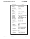
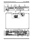
Connectors, Controls & Indicators (Continued)
#
CONNECTORS
1
,
CONTROLS &
INDICATORS
DESCRIPTION
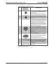
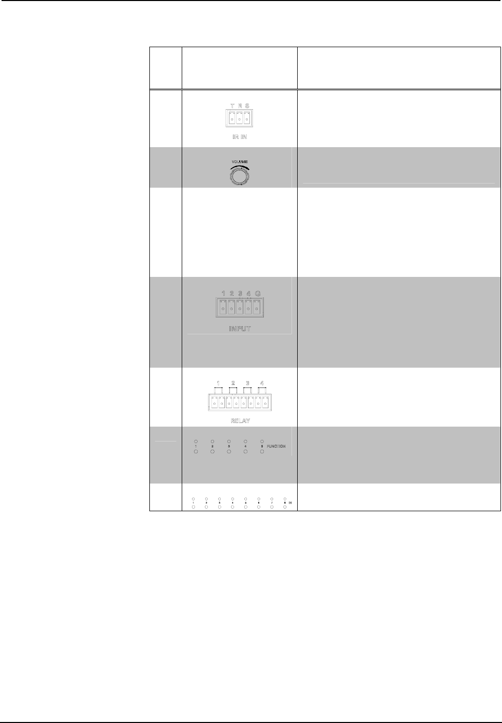
18
IR IN
(1) 3-pin 3.5 mm detachable terminal block;
For connection of the CNXRMIRD IR Receiver
(sold separately);
Allows IR wireless control from Crestron or
third-party remotes using RC-5 IR commands.
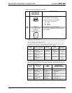
19
VOLUME CONTROL
(1) Continuous turn rotary encoder, adjusts
menu parameters, defaults to program audio
volume
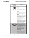
20 RGB DIP SWITCHES
(3) Banks of DIP switches (one per RGB input)
for configuring the horizontal and vertical sync
impedances of each RGB input. Each bank of
DIP switches can also be configured to
simulate the presence of a monitor to RGB
outputs that require a monitor to be connected.
For more information, refer to “Configure the
RGB Input Ports” on page 28.
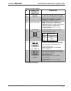
21
INPUT
(1) 5-pin 3.5 mm detachable terminal block;
Comprises (4) digital/contact closure inputs;
Rated for 0-24 Volts DC, referenced to GND;
Input Impedance: 2.2k ohms pulled up to 5
Volts DC;
Logic Threshold: 2.5 Volts DC nominal with
1 Volt hysteresis band
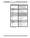
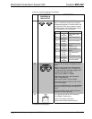
22
RELAY
(1) 8-pin 3.5 mm detachable terminal block;
Comprises (4) normally open, isolated relays;
Rated 1 Amp, 30 Volts AC/DC;
MOV arc suppression across contacts
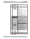
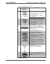
23
FUNCTION BUTTONS
(5) pushbuttons and red LEDs, programmable
for any control system function. When using
the out-of-the-box functionality, the buttons
control the projector screen and lighting (if
connected).
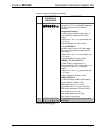
24
INPUT BUTTONS (8) pushbuttons and red LEDs, select input to
be routed.
(Continued on following page)
16 • Multimedia Presentation System 300: MPS-300 Operations Guide – DOC. 6529B