


Multimedia Presentation System 300 Crestron MPS-300
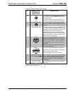
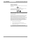
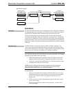
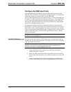
QM Network Topology
TPS-12G/15G-QM-L
MPS-300
QM
QM
QM
QM
QM
Origination Points
Endpoints
QM
Midpoints
MPS-300
MPS-300QM-MD7x2
MPS-300
TPS-12G/15G-QM-L
Installation
Ventilation
The MPS-300 should be used in a well-ventilated area. The venting holes should not
be obstructed under any circumstances. If the MPS-300 is hot to the touch, consider
using forced air ventilation and/or incrementing the spacing between units.
To prevent overheating, do not operate this product in an area that exceeds the
environmental temperature range listed in the table of specifications. Consideration
must be given if installed in a closed or multi-unit rack assembly since the operating
ambient temperature of the rack environment may be greater than the room ambient
temperature. Contact with thermal insulating materials should be avoided on all sides
of the unit.
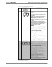
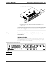
Rack Mounting
The MPS-300 can be mounted in a rack or stacked with other equipment. Two
“ears” are provided with the MPS-300 so that the unit can be rack mounted. These
ears must be installed prior to mounting. Complete the following procedure to attach
the ears to the unit. The only tool required is a #2 Phillips screwdriver.
WARNING: To prevent bodily injury when mounting or servicing this unit in a
rack, take special precautions to ensure that the system remains stable. The following
guidelines are provided to ensure your safety:
• When mounting this unit in a partially filled rack, load the rack from the
bottom to the top with the heaviest component at the bottom of the rack.
• If the rack is provided with stabilizing devices, install the stabilizers before
mounting or servicing the unit in the rack.
NOTE: Reliable earthing of rack-mounted equipment should be maintained.
Particular attention should be given to supply connections other than direct
connections to the branch circuit (e.g. use of power strips).
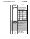
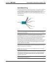
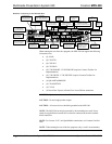
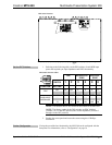
To install the ears:
1. There are screws that secure each side of the MPS-300 top cover. Using a
#2 Phillips screwdriver, remove the three screws closest to the front panel
from one side of the unit. Refer to the diagram following step 3 for a
detailed view.
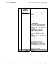
2. Position a rack ear so that its mounting holes align with the holes vacated
by the screws in step 1.
3. Secure the ear to the unit with three screws from step 1, as shown in the
following diagram.
24 • Multimedia Presentation System 300: MPS-300 Operations Guide – DOC. 6529B