


Crestron TPS-12G/15G/17G-QM Isys
®
G-Series Touchpanels
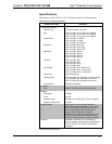
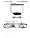
Connectors, Controls & Indicators
#
CONNECTORS
1
,
CONTROLS &
INDICATORS
DESCRIPTION
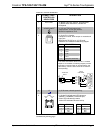
1 BUTTONS
2
(4) Backlit “hard key” buttons, programmable
(1) Backlit hard reset button, reboots the
touchpanel
2
HEADPHONES
3
(1) 3.5 mm TRS mini phone jack;
Output power: 12 mW per channel;
Minimum impedance: 32 Ω
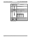
(1) 6-pin RJ-11 female;
Computer console, touch output or mouse/touch
input port;
Bidirectional RS-232 up to 115.2k baud;
Hardware and software handshaking support
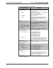
PIN # DESCRIPTION
1 CTS
2 GND
3 RXD
4 TXD
5 RTS
6 N/C (Not connected)
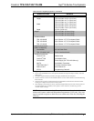
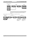
In the event that modular cables or an RJ-11 to DB9F
adapter is not available, the following diagram provides
information so that the cable can be fabricated on site.
(Alternatively, Crestron cable number STCP-502PC is
sold separately.)
3
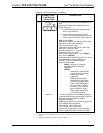
RS-232
1
2
3
4
5
6
7
8
9
1
3
6
5
4
2
2
3
5
7
8
1
CTS
GND
RXD
TXD
RTS
n/c
TO PC
COM PORT
TO RS-232
PORT
Part #
748047-1
Part #
641337
Part #
AWC10152-A
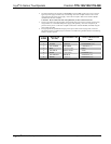
4
G
(1) 6-32 screw, chassis ground lug
5
LAN
GREEN
LED
YELLOW
LED
PIN 8
PIN 1
(1) 8-wire RJ-45 with two LED indicators;
10BASE-T/100BASE-TX Ethernet port;
Green LED indicates link status;
Yellow LED indicates Ethernet activity
PIN SIGNAL PIN SIGNAL
1 TX + 5 N/C
2 TX - 6 RC -
3 RC+ 7 N/C
4 N/C 8 N/C
(Continued on following page)
Operations Guide – DOC. 6415B Isys
®
G-Series Touchpanels: TPS-12G/15G/17G-QM • 15