


Crestron TPS-12G/15G/17G-QM Isys
®
G-Series Touchpanels
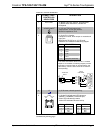
NOTE: Do not untwist the two wires in a single pair for more than 1/3-1/2”
(0.84-1.27 cm) when making a connection. The twists are critical to canceling out
interference between the wires.
The aggregate cable length of a signal path originating at a QM transmitter and
terminating at the TPS-12G/15G/17G-QM must not exceed 450 feet (137 meters).
Video signals may experience a loss of quality over very long lengths of cable. This
phenomenon is due to the added resistance and capacitance of longer cable lengths
and is not peculiar to either Crestron and/or QuickMedia systems. To ensure
sufficient bandwidth, the maximum aggregate cable length should not exceed 450
feet. The use of lower-resolution signals may allow increased cable length but must
be tested by the installer with the sources to be used. The QM pin assignment is
based on the EIA/TIA 568B RJ-45 Jack standard.
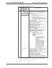
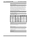
NOTE: QM IN 2 does not have delay skew compensation (as does QM IN 1), so
the maximum cable length varies based upon resolution and should not exceed 450
feet (137 meters) for standard definition video. Refer to the QM Input #2 Maximum
Cable Length table on that follows.
QM Input # 2 Maximum Cable Length
SIGNAL TYPE RESOLUTION MAXIMUM CABLE
LENGTH* (FEET)
Video/S-video 480i/576i 450
Component 480p/576p 300
Component 720p 300
Component 1080i 300
RGB 1024 x 768 @ 75 Hz 69
RGB 1280 x 1024 @ 75 Hz 40
RGB 1600 x 1200 @ 60 Hz 30
RGB 640 x 480 @ 60 Hz 216
RGB 800 x 600 @ 60Hz 140
RGB 1024 x 768 @ 60Hz 84
RGB 1280 x 768 @ 60Hz 70
* With CresCAT-QM cable, available from Crestron. Using other may adversely affect performance and
is not recommended.
NOTE: When transmitting S-video, luminance uses the green video pathway and
chrominance uses the red video pathway. When transmitting composite video, the
signal is carried on the blue video pathway.
NOTE: When using CresCAT-QM wiring, four additional wires are included for
making Cresnet connections.
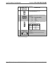
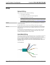
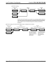
When connecting multiple QM devices, the route between a QM origination point
(transmitter) and a QM endpoint (receiver) cannot have more than two midpoints
(e.g. QM-MD7x2 or other QM switchers). Refer to the following illustration when
configuring a QM network.
NOTE: The aggregate length from transmitter to receiver cannot have a delay skew
of more than 22 ns.
Operations Guide – DOC. 6415B Isys
®
G-Series Touchpanels: TPS-12G/15G/17G-QM • 21