


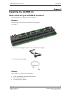
Unpacking the UCERB 24
As with any electronic device, you should take care while handling to avoid damage from static
electricity. Before removing the UCERB 24 from its packaging, ground yourself using a wrist strap or
by simply touching the computer chassis or other grounded object to eliminate any stored static charge.
If your UCERB 24 is damaged, notify CyberResearch, Inc. immediately by phone, fax, or e-mail.
Phone: 203.483.8815.
Fax: 203.483.9024 to the attention of Tech Support
Email: techsupport@cyberresearch.com
.
Installing the UCERB 24
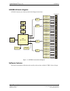
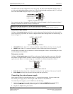
The UCERB 24 has two on-board switches that you set to configure the relay logic polarity and the
resistor pull-up/down configuration. Configure these switches before you connect the external power
supply to the UCERB 24. Factory-configured default settings are listed in Table 2-1. Refer to Figure 3.1
for the location of each switch on the UCERB 24.
Configuring the hardware switches
The UCERB 24 has two on-board switches that you set to configure the relay control logic polarity and
the
relay power-on state. Factory-configured default settings are listed in Table 2.1 Refer to Figure 3.1 for
the location of each switch on the UCERB 24.
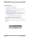
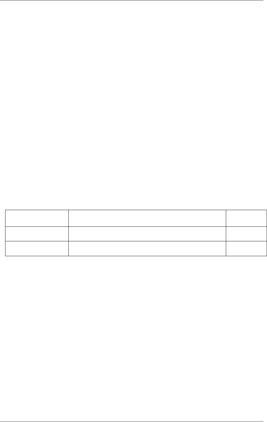
Board label Description Default
setting
INVERT NON-INVERT
S1
Configures the relay control logic parity per relay bank for invert or
non-invert logic.
Non-invert
Pull DOWN PULL UP
S2
Configures the relay power-on state per relay bank for pull-up or
pull-down.
Pull-down
Table 2-1. Default switch configuration
UCERB 24 CyberResearch
®
Digital I/O
6 ©Copyright 2005 CyberResearch, Inc.