


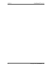
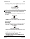
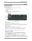
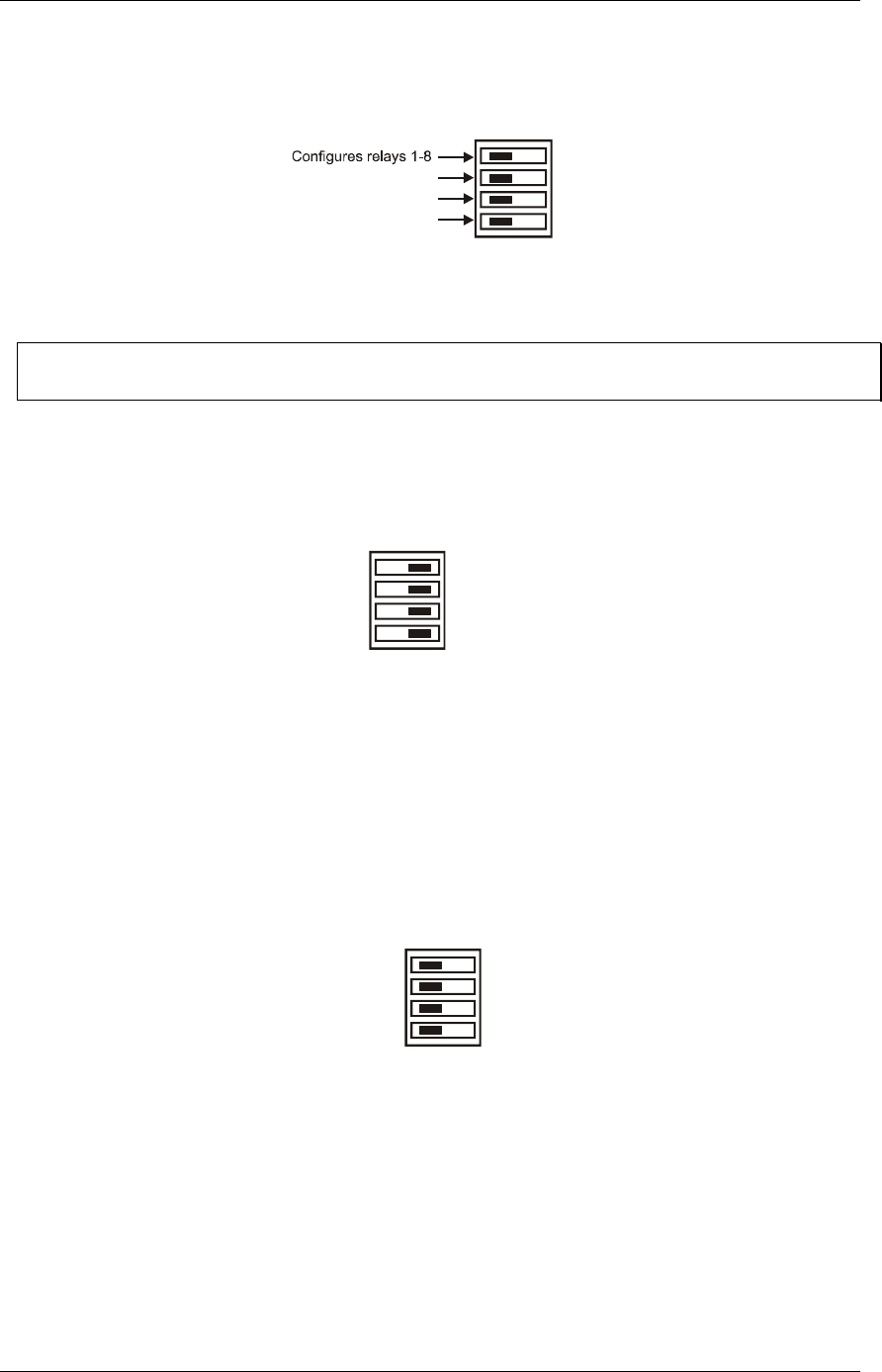
Each DIP switch sets the configuration of one relay group. The DIP switch labeled A configures relays 1
to 8, the switch labeled B configures relays 9 to 16, the switch labeled CL configures relays 17 to 20, and
the switch labeled
CH configures relays 21 to 24 ( ). Figure 2-2
Figure 2-2. Typical board switch
Configures 9-16relays
Configures relays17-20
Configures relays21-24
CL
CH
A
B
Port A consists of relays 1 through 8, Port B consists of relays 9 through 16, Port CL consists of relays 17
through 20, and Port CH consists of relays 21 through 24.
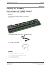
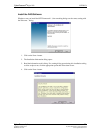
Remove from the enclosure to access the on-board switches
To change the configuration of a switch, you must first remove the UCERB 24 from the enclosure.
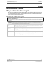
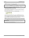
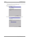
Relay control logic polarity
Configure the
Invert/non-invert switch (S1) to set the relay control logic polarity for each relay bank for
invert or non-invert. By default, this switch is shipped with all banks configured for non-inverted logic, as
shown in . Figure 2-3
Figure 2-3. Relay logic switch S1
NON-INVERTINVERT
S1
CL
CH
A
B
NON-INVERT mode: when "0" is written or read back via the USB bus, the relays are not energized.
INVERT mode: when "0" is written or read back via the USB bus, the relays are energized.
Switch settings for polarity can be read back via software through the USB bus. Switch settings for S1 do
not affect the power-on condition.
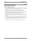
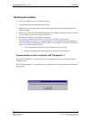
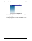
Relay power-on state
Configure the
Pull-up/pull-down switch (S2) to set the state of each relay bank at power-up. By default,
this product is shipped with the switch for all banks configured for pull-down (relays inactive at power
up), as shown in . Switch settings can be read back via software through the USB bus. Figure 2-4
Figure 2-4. Resistor pull-up/down switch S2
S2
PULL UPPULL DOWN
CL
CH
A
B
PULL-UP: the relays are put into an energized state at power-up, regardless of the state of switch S1
PULL-DOWN: the relays are put into a non-energized state at power-up.
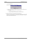
Connecting the external power supply
Power to the UCERB 24 is provided with the 9 V, 3 A external power supply. You must connect the
the external power supply before connecting the USB connector to the UCERB 24.
To connect the power supply to your UCERB 24, do the following:
1.
2.
Connect the external power cord to the power connector labeled POWER IN on the UCERB 24
enclosure (
PWR IN on the board). Refer to for the location of this connector. Figure 3-1
Plug the AC adapter into a power outlet.
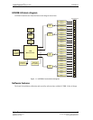
CyberResearch
®
Digital I/O UCERB 24
CyberResearch, Inc. 7
25 Business Park Drive P: (203) 483-8815; F: (203) 483-9024
Branford, CT USA www.cyberresearch.com