


1.
2.
3.
Connect the POWER OUT connector on the connected module to the POWER IN connector on the
new module.
This step is required only if you plan to daisy chain power to another module.
Connect the
USB OUT connector on the connected module to the USB IN connector on the new
module.
To add another module, repeat steps 1-2, with the module you just connected now being the
connected module.
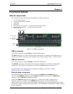
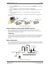
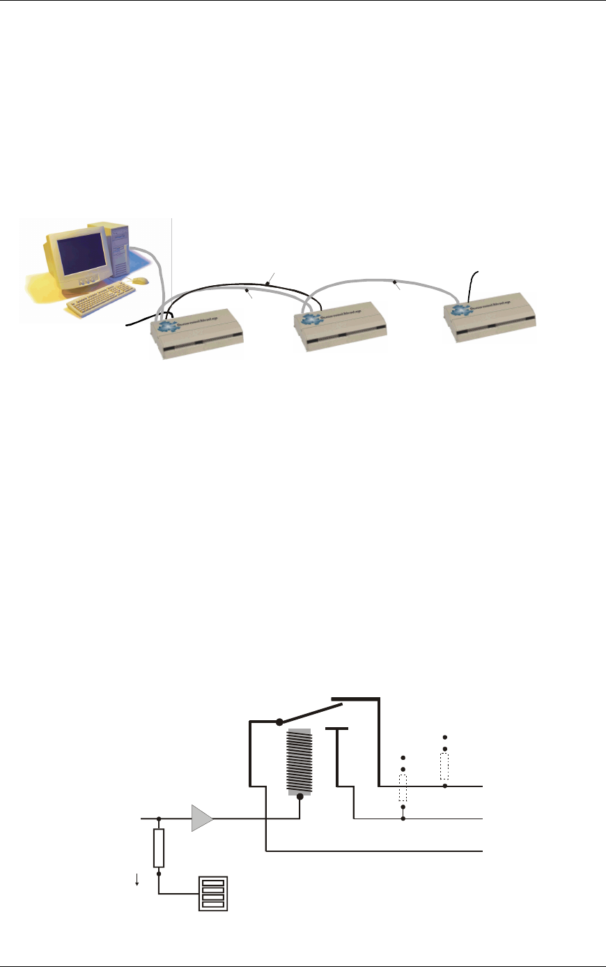
A daisy chain example is shown in . Note that the last board in the chain is supplied with
external power.
Figure 3-5
Figure 3-5. Daisy chain connections
USB port to
USB IN
USB OUT
to USB IN
POWER OUT to
POWER IN
USB OUT
to USB IN
CB
-
PWR
-
9V3A supply
to
POWER IN
UCERB 24 power supply
to POWER IN
Power limitations using multiple UCERB 24 devices
When daisy chaining additional CyberResearch products to the UCERB 24, you must ensure
that you provide adequate power to each board that you connect. The UCERB 24 is powered with a
9 VDC nominal, 3.0 A external power supply.
Voltage drop
A drop in voltage occurs with each board connected in a daisy chain system. The voltage drop between
the power supply input and the daisy chain output is 0.5 V maximum. Factor in this voltage drop when
you configure a daisy chain system to ensure that at least 6.0 VDC is provided to the last board in
the chain.
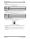
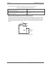
Relay configuration
You can install a pull-up or pull-down resistor at the NO and NC terminals on each relay. Note that the
pull-up resistors are tied to the 5 V power and should be considered when calculating the power budget.
The relay configuration is illustrated in the following schematic
User-installed
pull-up / pull-down resistor
GND
+5
Screw
terminals
(3 per
relay)
GND
+5
C
NO NC
Digital output
from the user
Buffer/
driver
10 k
resistor
Pull-up/pull-down
switch S2
Figure 3-6. Relay configuration
CyberResearch
®
Digital I/O UCERB 24
CyberResearch, Inc. 17
25 Business Park Drive P: (203) 483-8815; F: (203) 483-9024
Branford, CT USA www.cyberresearch.com