


Power
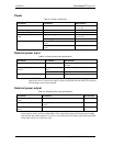
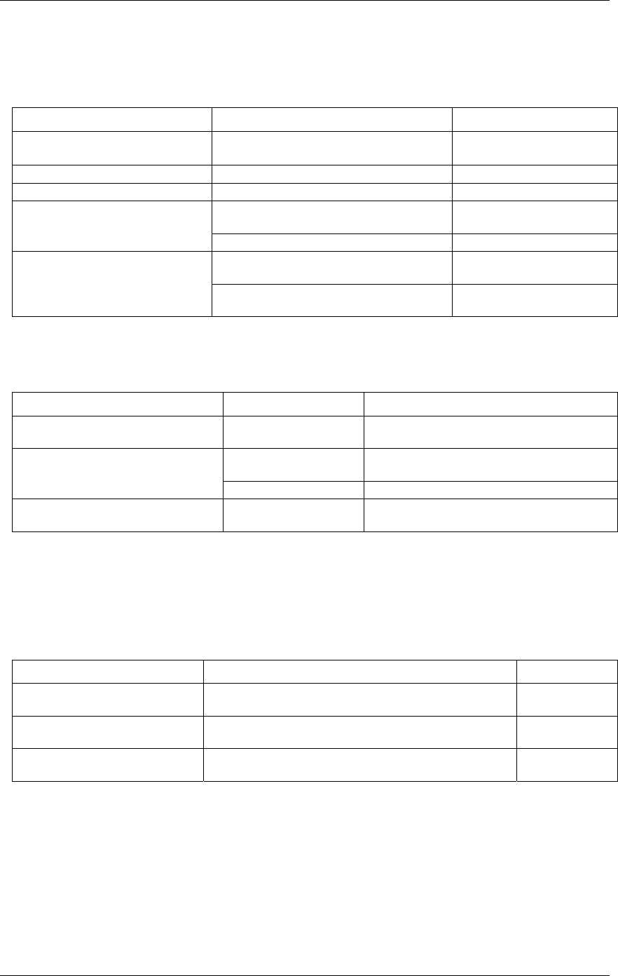
Table 4-2. Power specifications
Parameter Conditions Specification
USB +5 V input voltage range 4.75 V min. to
5.25 V max.
USB +5 V supply current All modes of operation 10 mA max
External power supply (required) 9 V ±10% @ 3 A
V
ext
< 6.0 V
,
V
ext
> 12.5 V
PWR LED = Off
(power fault)
Voltage supervisor limits - PWR
LED
6.0 V < V
ext
< 12.5 V PWR LED = On
All relays on, 100 mA downstream hub
power
1.5 A typ, 1.8 A max
External power consumption
All relays off, 100 mA downstream hub
power
230 mA typ, 270 mA max
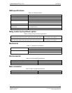
External power input
Table 4-3. External power input specifications
Parameter Conditions Specification
External power input
+6.0 VDC to 12.5 VDC (9 VDC power supply
included).
6.0 V > V
ext
or V
ext
>
12.5 V
PWR LED = Off (power fault)
Voltage supervisor limits - PWR LED
(Note 1)
6.0 V < V
ext
< 12.5 V PWR LED = On
External power adapter (included)
+9 V ±10%, @ 3 A
Note 1: The UCERB 24 monitors the external +9 V power supply voltage with a voltage
supervisory circuit. If this power supply exceeds its specified limit, the PWR LED will turn
off indicating a power fault condition.
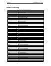
External power output
Table 4-4. External power output specifications
Parameter Conditions Specification
External power output - current
range
4.0 A max.
External power output (Note 2)
Voltage drop between power input and daisy chain power
output
0.5 V max
Compatible cable(s) for daisy
chain
C-MAPWR-x
x = 2 , 3 or 6
feet
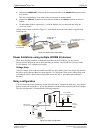
Note 2: The daisy chain power output option allows multiple boards to be powered from a single
external power source in a daisy chain fashion. The voltage drop between the module power supply
input and the daisy chain output is 0.5 V max. Users must plan for this drop to ensure the last module
in the chain will receive at least 6.0 VDC.
UCERB 24 CyberResearch
®
Digital I/O
20 ©Copyright 2005 CyberResearch, Inc.