


USB LED
The USB LED indicates the communication status of the UCERB 24. It uses up to 5 mA of current and
cannot be disabled. Ta explains the USB LED function. ble 3-2
Table 3-2. USB LED Illumination
USB LED
illumination
Indication
Steady green The UCERB 24 is connected to a computer or external USB hub.
Pulsing green
Initial communication is established between the UCERB 24 and the computer, or data is
being transferred.
PWR LED
The UCERB 24 incorporates an on-board voltage supervisory circuit that monitors the external 9 V
power. If the input voltage falls outside of the specified range, the
PWR LED shuts off.
explains the function of the PWR LED.
Table 3-3
Table 3-3. PWR LED Illumination
PWR LED
illumination
Indication
Steady green External power is supplied to the UCERB 24.
Off
Power is not supplied by the external supply, or a power fault has occurred. A power fault
occurs when the input power falls outside of the specified voltage range of the external supply
(6.0 V to 12.5 V).
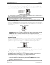
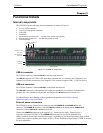
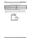
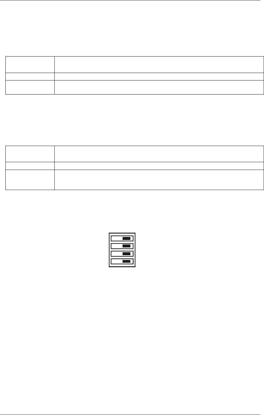
Invert/non-invert switch (S1)
The Invert/non-invert switch (S1) sets the relay control logic per relay bank to either inverted or non-
inverted. By default, switch S1 is configured for non-invert (see ). Figure 3-2
Figure 3-2. Switch S1 default configuration
NON-INVERTINVERT
S1
CL
CH
A
B
The switch labeled A configures relays 1 through 8, the switch labeled B configures relays 9 through 16,
the switch labeled
CH configures relays 17 through 20, the switch labeled CL configures relays 21
through 24.
NON-INVERT: when "0" is written or read back via the USB bus, the relays are not energized.
INVERT: when "0" is written or read back via the USB bus, the relays are energized.
Switch settings do not affect the power-on condition. Use InstaCal to read the current logic setting for
each module group.
CyberResearch
®
Digital I/O UCERB 24
CyberResearch, Inc. 15
25 Business Park Drive P: (203) 483-8815; F: (203) 483-9024
Branford, CT USA www.cyberresearch.com