


Chapter 3
Functional Details
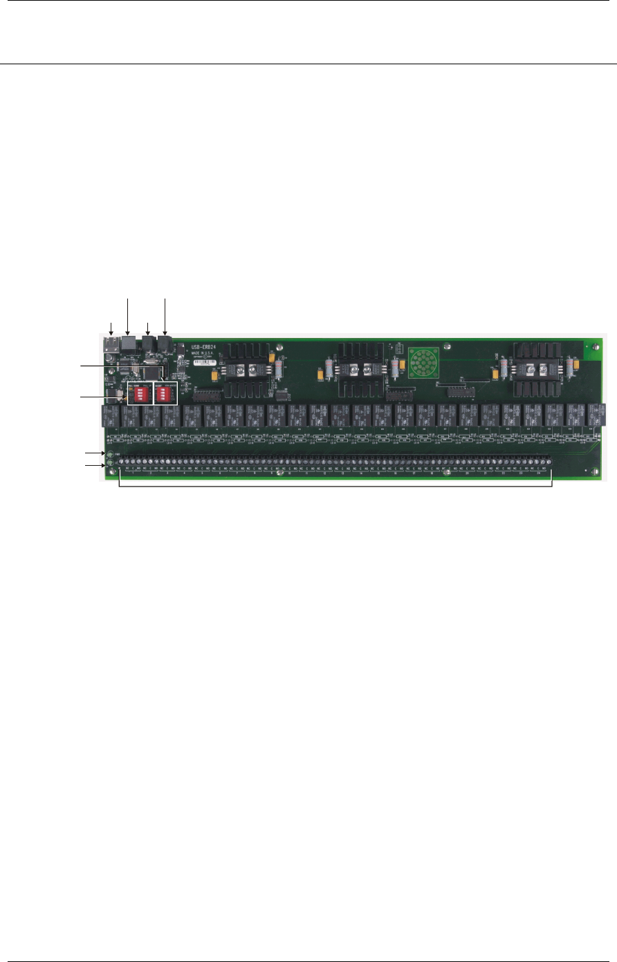
Internal components
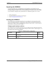
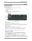
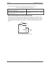
The UCERB 24 has the following internal components, as shown in Figure 3-1.
Two (2) USB connectors
Two (2) external power connectors
USB LED
PWR LED
Invert/non-invert switch (S1) — sets the relay control logic polarity
Pull-up/down switch (S2) — sets the relay power-on state
Screw terminals
Invert/non-invert
switch (S1)
PWR LED
USB LED
USB IN
POWER
OUT
POWER IN
USB
OUT
Pull-up/pull-down
switch (S2)
Screw terminals
Figure 3-1. UCERB 24 components
USB in connector
The USB out connector is labeled USB IN on the board and enclosure.
The USB IN connector is a USB 2.0 full-speed input connector that you connect to the USB port on your
computer (or USB hub connected to your computer). This connector supports USB 1.1, USB 2.0 devices.
USB out connector
The USB out connector is labeled USB OUT on the board and enclosure.
The
USB OUT connector is a downstream hub output port intended for use with other CyberResearch
products only. The USB hub is self-powered, and can provide
100 mA maximum current at 5 V.
For information on daisy chaining to other CyberResearch products, refer to Daisy chaining
additional modules to the USB-ERB08.
External power connectors
The UCERB 24 has two external power connectors labeled POWER IN and POWER OUT on the
enclosure. The
POWER IN connector is labeled PWR IN and P19 on the board, and the POWER OUT
connector is labeled PWR OUT and P20 on the board.
Connect the
POWER IN connector to the supplied +9 V external power supply. External power is
required to operate the UCERB 24. The
POWER OUT connector lets you power additional daisy
chained products from a single external power supply. Depending on your load requirements, daisy chained
products may require a separate power supply. Refer to "Power limitations using multiple UCERB 24 devices"
for more information.
UCERB 24 CyberResearch
®
Digital I/O
14 ©Copyright 2005 CyberResearch, Inc.