


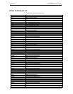
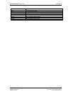
The relay contacts associated that are with each relay location are listed in . Table 3-4
Table 3-4. Relay locations and associated contacts
R35, R36, R41, R43, R45, R47, R49, R51, R87, R89,
R91, R93, R96, R98, R100, R102, R103, R105, R107,
R109, R112, R114, R116, R118
Relays NO contact pull-up (to USB +5 V) / pull-down,
user installed.
R37, R40, R42,R44, R46, R48, R50, R52, R88, R90, R92,
R94, R95, R97, R99, R101, R104, R106, R108, R110,
R111, R113, R115, R117
Relays NC contact pull-up (to USB +5 V) / pull-down,
user installed
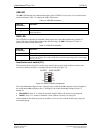
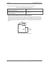
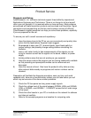
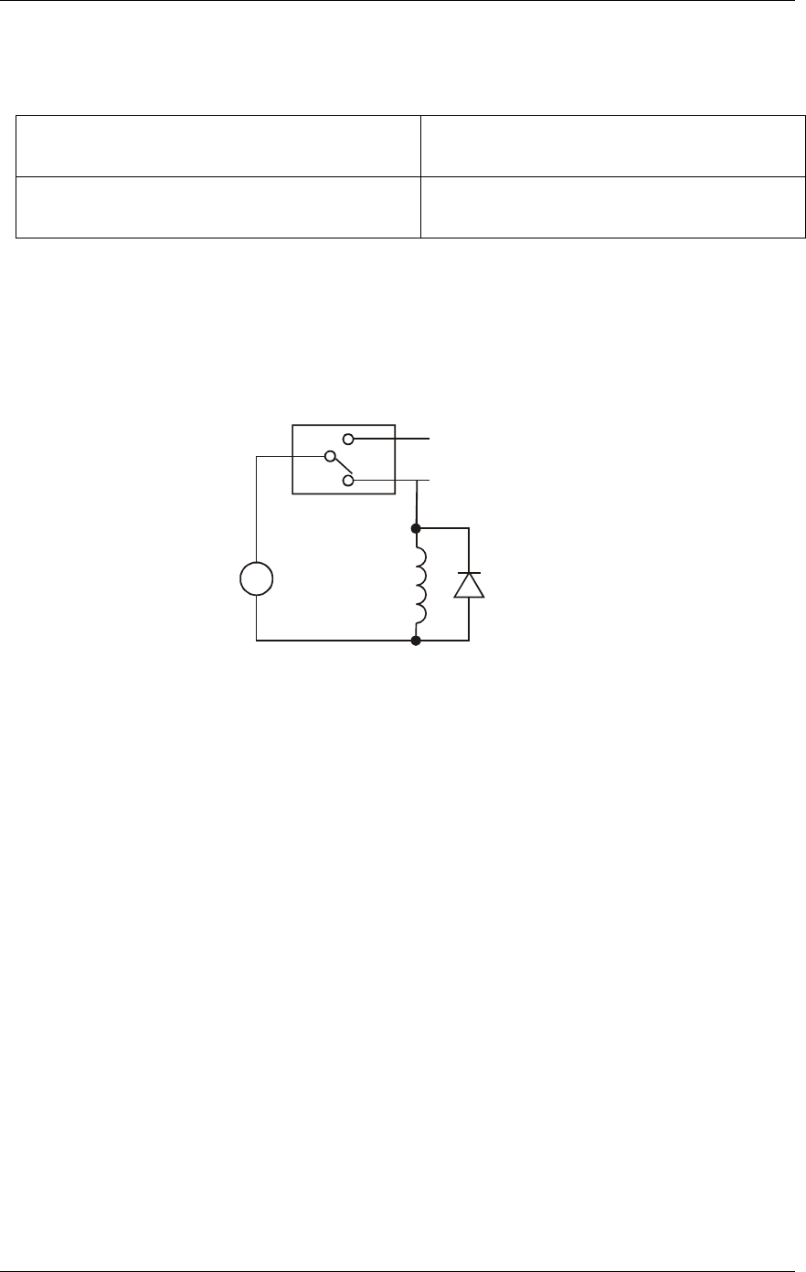
Relay contact protection circuit for inductive loads
When you connect an inductive load to a relay, energy stored in the inductive load can induce a large
voltage surge when you switch the relay. This voltage can severely damage the relay contacts. To limit
the voltage surge across the inductive load in a DC circuit, install a kickback diode across the inductive
load. Refer to the contact protection circuit in Fi . For AC loads, install a metal oxide varistor
(MOV).
gure 3-7
Figure 3-7. Relay contact protection circuit
C
V
Inductive
Load
Kickback
Diode
NC
+
-
NO
Relay
UCERB 24 CyberResearch
®
Digital I/O
18 ©Copyright 2005 CyberResearch, Inc.