


UMDAS 0802DA User's Guide Functional Details
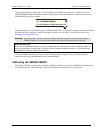
USB connector
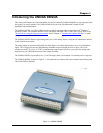
The USB connector is on the right side of the UMDAS 0802DA. This connector provides +5 V power and
communication. The voltage supplied through the USB connector is system-dependent, and may be less than
5 V. No external power supply is required.
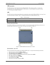
LED
The LED on the front of the housing indicates the communication status of the UMDAS 0802DA. It uses up to 5 mA
of current and cannot be disabled. Table 3-1 defines the function of the UMDAS 0802DA's LED.
Table 3-1. LED Illumination
LED Illumination Indication
Steady green The UMDAS 0802DA is connected to a computer or external USB hub.
Blinks continuously Data is being transferred.
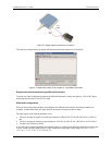
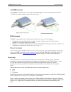
Screw terminal wiring
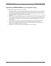
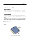
The UMDAS 0802DA has two rows of screw terminals—one row on the top edge of the housing, and one row on
the bottom edge. Each row has 20 connections. Pin numbers are identified in Fi . gure 3-2
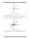
Figure 3-2. UMDAS 0802DA Screw terminal pin numbers
Screw terminal – pins 1-20
The screw terminals on the top edge of the UMDAS 0802DA (pins 1 to 20) provide the following connections:
! Eight analog input connections (
CH0 IN to CH7 IN)
! Two analog output connections (
D/A OUT 0 to D/A OUT 1)
! One external trigger source (
TRIG_IN)
! One SYNC terminal for external clocking and multi-unit synchronization (
SYNC)
! One voltage output source (
2.5VREF)
! Five analog ground connections (
AGND)
! One ground connection (
GND)
! One external event counter connection (
CTR)
3-2