


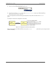

+5V+GND
Port A0
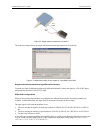
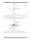
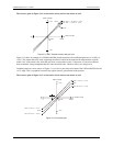
Figure 3-9. Schematic showing switch detection by digital channel Port A0
For more information on digital signal connections
For more information on digital signal connections and digital I/O techniques, available on the software CD
which accompanies your device.
Power terminals
The PC +5V connection (pin 30) draws power from the USB connector. This terminal is a 5 V output that is
supplied by the host computer. Refer to the "Main connector and pin out
" diagrams on page 3-3 for the location
of this pin.
Caution! The +5 V terminal is an output. Do not connect to an external power supply or you may damage
the UMDAS 0802DA and possibly the computer.
The maximum total output current that can be drawn from all UMDAS 0802DA connections (power, analog and
digital outputs) is 420 mA. This maximum applies to most personal computers and self-powered USB hubs.
Bus-powered hubs and notebook computers may limit the maximum available output current to 100 mA.
Just connecting the UMDAS 0802DA to your computer draws 80 mA of current from the USB +5 V supply. Once
you start running applications with the UMDAS 0802DA, each DIO bit can draw up to 2.5 mA, and each analog
output can draw 15 mA. The maximum amount of +5 V current available for experimental use, over and above
that required by the UMDAS 0802DA, is the difference between the total current requirement of the USB (based on
the application), and the allowed current draw of the PC platform (500 mA for desktop PCs and self-powered
hubs, or 100 mA for bus-powered hubs and notebook computers). With all outputs at their maximum output
current, you can calculate the total current requirement of the UMDAS 0802DA USB +5 V supply as follows:
(UMDAS 0802DA @ 80 mA) + (16 DIO @ 2.5 mA ea) + (2 AO @ 15 mA ea ) = 150 mA
For an application running on a PC or powered hub, the maximum available excess current is
500 mA − 150 mA = 350 mA. This number is the total maximum available current at the PC +5 V screw
terminals. CyberResearch, Inc. highly recommends that you figure in a safety factor of 20% below this
maximum current loading for your applications. A conservative, safe user maximum in this case would be
280 mA.
Since laptop computers typically allow up to 100 mA, the UMDAS 0802DA in a fully-loaded configuration may be
above that allowed by the computer. In this case, you must determine the per-pin loading in the application to
ensure that the maximum loading criteria is met. The per-pin loading is calculated by simply dividing the +5 V
by the load impedance of the pin in question.
External trigger terminal
The TRIG_IN connection (pin 18) can be configured for either rising or falling edge. Refer to the "Main
connector and pin out" diagrams on page 3-3 for the location of this pin.
Counter terminal
The CTR connection (pin 20) is input to the 32-bit external event. Refer to the "Main connector and pin out"
diagrams on page 3-3 for the location of this pin. The internal counter increments when the TTL levels
transition from low to high. The counter can count frequencies of up to 1 MHz.
3-7
UMDAS 0802DA User's Guide Functional Details