


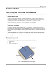

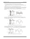
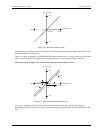

Pin 3
AGND
Pin 1
CH0
Figure 3-3. Single-ended measurement connection
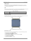
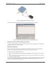
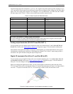
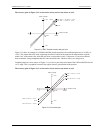
The following example shows the single-ended measurement data acquired by TracerDAQ.
Figure 3-4. Measurement data (9 volt) plotted on TracerDAQ's Strip Chart
Single-ended measurements using differential channels
To perform a single-ended measurement using differential channels, connect the signal to "CHn IN HI" input,
and ground the associated "CHn IN LO" input.
Differential configuration
When all of the analog input channels are configured for differential input mode, four analog channels are
available. In differential mode, the input signal is measured with respect to the low input.
The input signal is delivered through three wires:
! The wire carrying the signal to be measured connects to CH0 IN HI, CH1 IN HI, CH2 IN HI, or CH3 IN
HI.
! The wire carrying the reference signal connects to CH0 IN LO, CH1 IN LO, CH2 IN LO, or CH3 IN LO.
! The third wire connects to GND.
A low-noise precision programmable gain amplifier (PGA) is available on differential channels to provide gains
of up to 20 and a dynamic range of up to 14-bits. Differential mode input voltage ranges are ±20 V, ±10 V,
±5 V, ±4 V, ±2.5 V, ±2.0 V, 1.25 V, and ±1.0 V.
3-4
UMDAS 0802DA User's Guide Functional Details