


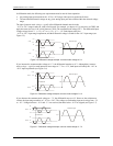
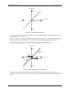

Since the analog inputs are restricted to a −10 V to +20 V signal swing with respect to ground, all ranges except
±20V can realize a linear output for any differential signal with zero common mode voltage and full scale signal
inputs. The ±20 V range is the exception. You cannot put −20 V on CHHI and 0 V on CHLO since this violates
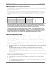
the input range criteria. shows some possible inputs and the expected results. Table 3-2
Table 3-2. Sample inputs and differential results
CHHI CHLO Result
−20 V 0 V In Valid
−15 V +5 V In Valid
−10 V 0 V −10 V
−10 V +10 V −20 V
0 V +10 V −10 V
0 V +20 V −20 V
+10 V −10 V +20 V
+10 V 0 V +10 V
+15 V −5 V +20 V
+20 V 0 +20 V
For more information on analog signal connections
For more information on single-ended and differential inputs, refer to the Guide to Signal Connections (this
document is available on the software CD which accompanies your device.
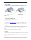
Analog output terminals (D/A OUT 0 and D/A OUT 1)
You can connect up to two analog output connections to the screw terminal pins 13 and 14 (D/A OUT 0 and
D/A OUT 1). Refer to the "Main connector and pin out" diagrams on page 3-3 for the location of these pins.
Each channel can be paced individually at rates up to 10,000 updates per second. Both channels can be paced
simultaneously using the same time base at 5000 updates per channel. The 0-4.096 V output range provides a
convenient 1 mV per LSB when setting the output voltage levels.
Digital I/O terminals (Port A0 to A7, and Port B0 to B7)
You can connect up to 16 digital I/O lines to the screw terminal containing pins 21 to 40 (Port A0 to Port A7,
and Port B0 to Port B7.) Refer to the "Main connector and pin out
" diagrams on page 3-3 for the location of
these pins. You can configure each digital port for either input or output.
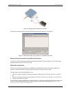
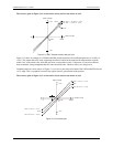
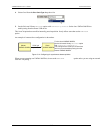
When you configure the digital bits for input, you can use the digital I/O terminals to detect the state of any
TTL level input. Refer to the switch shown in Figure and the schematic shown in . If the switch is
set to the +5 V input, Port A0 reads TRUE (1). If you move the switch to GND, Port A0 reads FALSE.
3-8
Figure 3-8. Digital connection Port A0 detecting the state of a switch
Figure 3-9
4
3-6
UMDAS 0802DA User's Guide Functional Details