


CY7C0850AV, CY7C0851AV
CY7C0852AV, CY7C0853AV
Document #: 38-06070 Rev. *H Page 12 of 32
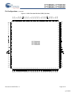
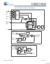
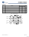
IEEE 1149.1 Serial Boundary Scan (JTAG)
[13]
The CY7C0850AV/CY7C0851AV/CY7C0852AV/CY7C0853AV
incorporates an IEEE 1149.1 serial boundary scan test access
port (TAP). The TAP controller functions in a manner that does
not conflict with the operation of other devices using
1149.1-compliant TAPs. The TAP operates using
JEDEC-standard 3.3V I/O logic levels. It is composed of three
input connections and one output connection required by the test
logic defined by the standard.
Performing a TAP Reset
A reset is performed by forcing TMS HIGH (V
DD
) for five rising
edges of TCK. This reset does not affect the operation of the
devices, and may be performed while the devices are operating.
An MRST
must be performed on the devices after power up.
Performing a Pause/Restart
When a SHIFT-DR PAUSE-DR SHIFT-DR is performed the scan
chain outputs the next bit in the chain twice. For example, if the
value expected from the chain is 1010101, the device outputs a
11010101. This extra bit causes some testers to report an
erroneous failure for the devices in a scan test. Therefore the
tester should be configured to never enter the PAUSE-DR state.
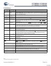
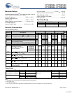
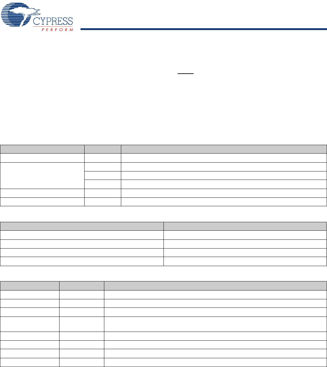
Table 4. Identification Register Definitions
Instruction Field Value Description
Revision Number (31:28) 0h Reserved for version number.
Cypress Device ID
(27:12) C001h Defines Cypress part number for the CY7C0851AV
C002h Defines Cypress part number for the CY7C0852AV and CY7C0853AV
C092h Defines Cypress part number for the CY7C0850AV
Cypress JEDEC ID (11:1) 034h Allows unique identification of the DP family device vendor.
ID Register Presence (0) 1 Indicates the presence of an ID register.
Table 5. Scan Registers Sizes
Register Name Bit Size
Instruction 4
Bypass 1
Identification 32
Boundary Scan n
[14]
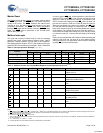
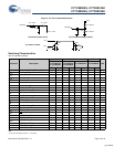
Table 6. Instruction Identification Codes
Instruction Code Description
EXTEST 0000 Captures the Input/Output ring contents. Places the BSR between the TDI and TDO.
BYPASS 1111 Places the BYR between TDI and TDO.
IDCODE 1011 Loads the IDR with the vendor ID code and places the register between TDI and TDO.
HIGHZ 0111 Places BYR between TDI and TDO. Forces all CY7C0851AV/CY7C0852AV/
CY7C0853AV output drivers to a High-Z state.
CLAMP 0100 Controls boundary to 1/0. Places BYR between TDI and TDO.
SAMPLE/PRELOAD 1000 Captures the input/output ring contents. Places BSR between TDI and TDO.
NBSRST 1100 Resets the non-boundary scan logic. Places BYR between TDI and TDO.
RESERVED All other codes Other combinations are reserved. Do not use other than the above.
Notes
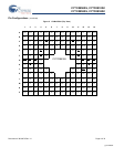
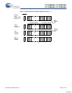
12.The “X” in this diagram represents the counter upper bits.
13.Boundary scan is IEEE 1149.1-compatible. See “Performing a Pause/Restart” for deviation from strict 1149.1 compliance.
14.See details in the device BSDL files.
[+] Feedback