


CY7C0850AV, CY7C0851AV
CY7C0852AV, CY7C0853AV
Document #: 38-06070 Rev. *H Page 24 of 32
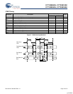
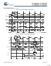
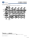
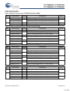
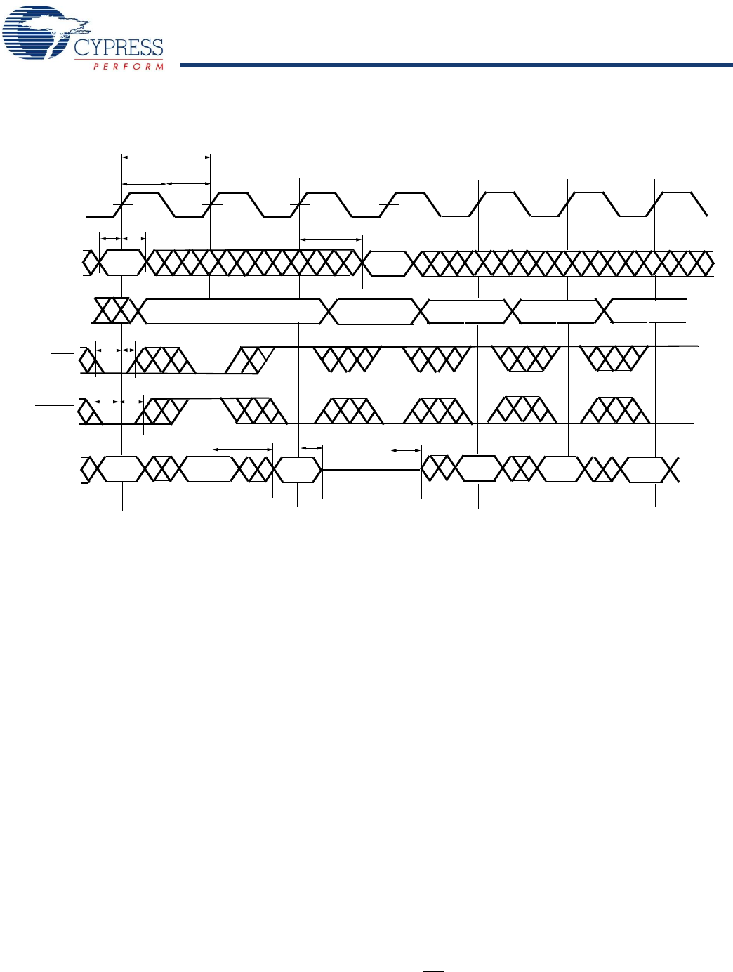
Figure 20. Readback State of Address Counter or Mask Register
[35, 36, 37, 38]
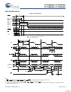
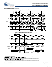
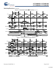
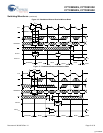
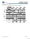
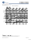
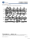
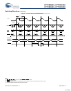
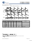
Switching Waveforms (continued)
CNTEN
CLK
t
CH2
t
CL2
t
CYC2
ADDRESS
ADS
A
n
Q
x-2
Q
x-1
Q
n
t
SA
t
HA
t
SAD
t
HAD
t
SCN
t
HCN
LOAD
ADDRESS
EXTERNAL
t
CD2
INTERNAL
ADDRESS
A
n+1
A
n+2
A
n
t
CKHZ
DATA
OUT
A
n*
Q
n+3
Q
n+1
Q
n+2
A
n+3
A
n+4
t
CKLZ
t
CA2
or t
CM2
READBACK
INTERNAL
COUNTER
ADDRESS
INCREMENT
EXTERNAL
A
0
–A
16
Notes
35.CE
0
= OE = B0 – B3 = LOW; CE
1
= R/W = CNTRST = MRST = HIGH.
36.Address in output mode. Host must not be driving address bus after t
CKLZ
in next clock cycle.
37.Address in input mode. Host can drive address bus after t
CKHZ
.
38.An * is the internal value of the address counter (or the mask register depending on the CNT/MSK
level) being Read out on the address lines.
[+] Feedback