CY7C601xx, CY7C602xx
Document 38-16016 Rev. *E Page 39 of 68
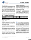
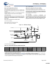
16.2.10 P0.1/CLKOUT Configuration
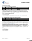
16.2.11 P0.2/INT0–P0.4/INT2 Configuration
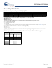
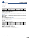
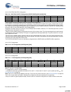
Table 16-7. P0.1/CLKOUT Configuration (P01CR) [0x06] R/W]
Bit # 7 6 5 4 3 2 1 0
Field CLK Output Int Enable Int Act Low TTL Thresh High Sink Open Drain Pull up Enable Output Enable
Read/Write R/W R/W R/W R/W R/W R/W R/W R/W
Default 0 0 0 0 000 0
This pin is shared between the P0.1 GPIO use and the CLKOUT pin for the external crystal oscillator. When the external oscillator
is enabled the settings of this register are ignored. When CLK output is set, the internally selected clock is sent out onto
P0.1CLKOUT pin.
The alternate function of the pin as the CLKOUT is only available in the CY7C601xx. When the external oscillator is enabled
(the XOSC Enable bit of the CLKIOCR Register is set—Table 12-4), the GPIO function of the pin is disabled.
The 50 mA sink drive capability is only available in the CY7C601xx. In the CY7C602xx, only 8 mA sink drive capability is available
on this pin regardless of the setting of the High Sink bit.
Bit 7: CLK Output
0 = The clock output is disabled.
1 = The clock selected by the CLK Select field (Bit [1:0] of the CLKIOCR Register—Table 12-4) is driven out to the pin.
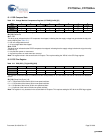
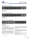
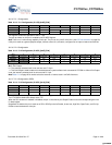
Table 16-8. P0.2/INT0–P0.4/INT2 Configuration (P02CR–P04CR) [0x07–0x09] [R/W]
Bit # 7 6 5 4 3 2 1 0
Field Reserved Int Act Low TTL Thresh Reserved Open Drain Pull up Enable Output Enable
Read/Write
– –
R/W R/W
–
R/W R/W R/W
Default 0 0 0 0 000 0
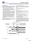
These registers control the operation of pins P0.2–P0.4 respectively. These pins are shared between the P0.2–P0.4 GPIOs and
the INT0–INT2. The INT0–INT2 interrupts are different from all other GPIO interrupts. These pins are connected directly to the
interrupt controller to provide three edge-sensitive interrupts with independent interrupt vectors. These interrupts occur on a
rising edge when Int Act Low is clear and on a falling edge when Int Act Low is set. These pins are enabled as interrupt sources
in the interrupt controller registers (Table 19-8 and Table 19-6).
To use these pins as interrupt inputs, configure them as inputs by clearing the corresponding Output Enable. If the INT0–INT2
pins are configured as outputs with interrupts enabled, firmware generates an interrupt by writing the appropriate value to the
P0.2, P0.3, and P0.4 data bits in the P0 Data Register.
Regardless of whether the pins are used as Interrupt or GPIO pins the Int Enable, Int Act Low, TTL Threshold, Open Drain, and
Pull up Enable bits control the behavior of the pin.
The P0.2/INT0–P0.4/INT2 pins are individually configured with the P02CR (0x07), P03CR (0x08), and P04CR (0x09) respec-
tively.
Note Changing the state of the Int Act Low bit generates an unintentional interrupt. When configuring these interrupt sources,
follow this procedure:
1. Disable interrupt source
2. Configure interrupt source
3. Clear any pending interrupts from the source
4. Enable interrupt source
[+] Feedback [+] Feedback


