


CY7C601xx, CY7C602xx
Document 38-16016 Rev. *E Page 54 of 68
19. Interrupt Controller
The interrupt controller and its associated registers allow the
user’s code to respond to an interrupt from almost every
functional block in the enCoRe II LV devices. The registers
associated with the interrupt controller are disabled either
globally or individually. The registers also provide a mechanism
for users to clear all pending and posted interrupts or clear
individual posted or pending interrupts.
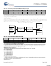
Table 19-1 lists all interrupts and the priorities that are available
in the enCoRe II LV devices.
19.1 Architectural Description
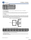
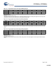
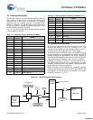
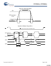
An interrupt is posted when its interrupt conditions occur. This
results in the flip-flop in Figure 19-1. clocking in a ‘1’. The
interrupt remains posted until the interrupt is taken or until it is
cleared by writing to the appropriate INT_CLRx register.
A posted interrupt is not pending unless it is enabled by setting
its interrupt mask bit (in the appropriate INT_MSKx register). All
pending interrupts are processed by the Priority Encoder to
determine the highest priority interrupt which is taken by the M8C
if the Global Interrupt Enable bit is set in the CPU_F register.
Disabling an interrupt by clearing its interrupt mask bit (in the
INT_MSKx register) does not clear a posted interrupt, nor does
it prevent an interrupt from being posted. It simply prevents a
posted interrupt from becoming pending.
Nested interrupts are accomplished by reenabling interrupts
inside an interrupt service routine. To do this, set the IE bit in the
Flag Register. A block diagram of the enCoRe II LV Interrupt
Controller is shown in Figure 19-1..
Figure 19-1. Interrupt Controller Block Diagram
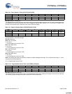
Table 19-1. Interrupt Priorities, Address, and Name
Interrupt
Priority
Interrupt
Address
Name
0 0000h Reset
1 0004h POR/LVD
2 0008h INT0
3 000Ch SPI Transmitter Empty
4 0010h SPI Receiver Full
5 0014h GPIO Port 0
6 0018h GPIO Port 1
7 001Ch INT1
8 0020h Reserved
9 0024h Reserved
10 0028h Reserved
11 002Ch Reserved
12 0030h Reserved
13 0034h 1 mS Interval timer
14 0038h Programmable Interval Timer
15 003Ch Timer Capture 0
16 0040h Timer Capture 1
17 0044h 16-bit Free Running Timer Wrap
18 0048h INT2
19 004Ch Reserved
20 0050h GPIO Port 2
21 0054h GPIO Port 3
22 0058h GPIO Port 4
23 005Ch Reserved
24 0060h Reserved
25 0064h Sleep Timer
Table 19-1. Interrupt Priorities, Address, and Name (contin-
Interrupt
Priority
Interrupt
Address
Name
Interrupt
Source
(Timer,
GPIO, etc.)
Interrupt Taken
or
Posted
Interrupt
Pending
Interrupt
GIE
Interrupt Vector
Mask Bit Setting
D
R
Q1
Priority
Encoder
M8C Core
Interrupt
Request
...
INT_MSKx
INT_CLRx Write
CPU_F[0]
...
[+] Feedback [+] Feedback