CY7C68053
Document # 001-06120 Rev *F Page 10 of 39
3.18.2 I
2
C Interface Boot Load Access
At power on reset the I
2
C interface boot loader loads the
VID/PID/DID and configuration bytes and up to 16 kBytes of
program/data. The available RAM spaces are 16 kBytes from
0x0000–0x3FFF and 512 bytes from 0xE000–0xE1FF. The
8051 is reset. I
2
C interface boot loads only occur after power
on reset.
3.18.3 I
2
C Interface General Purpose Access
The 8051 can control peripherals connected to the I
2
C bus
using the I2CTL and I2DAT registers. FX2LP18 provides I
2
C
master control only, it is never an I
2
C slave.
4.0 Pin Assignments
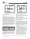
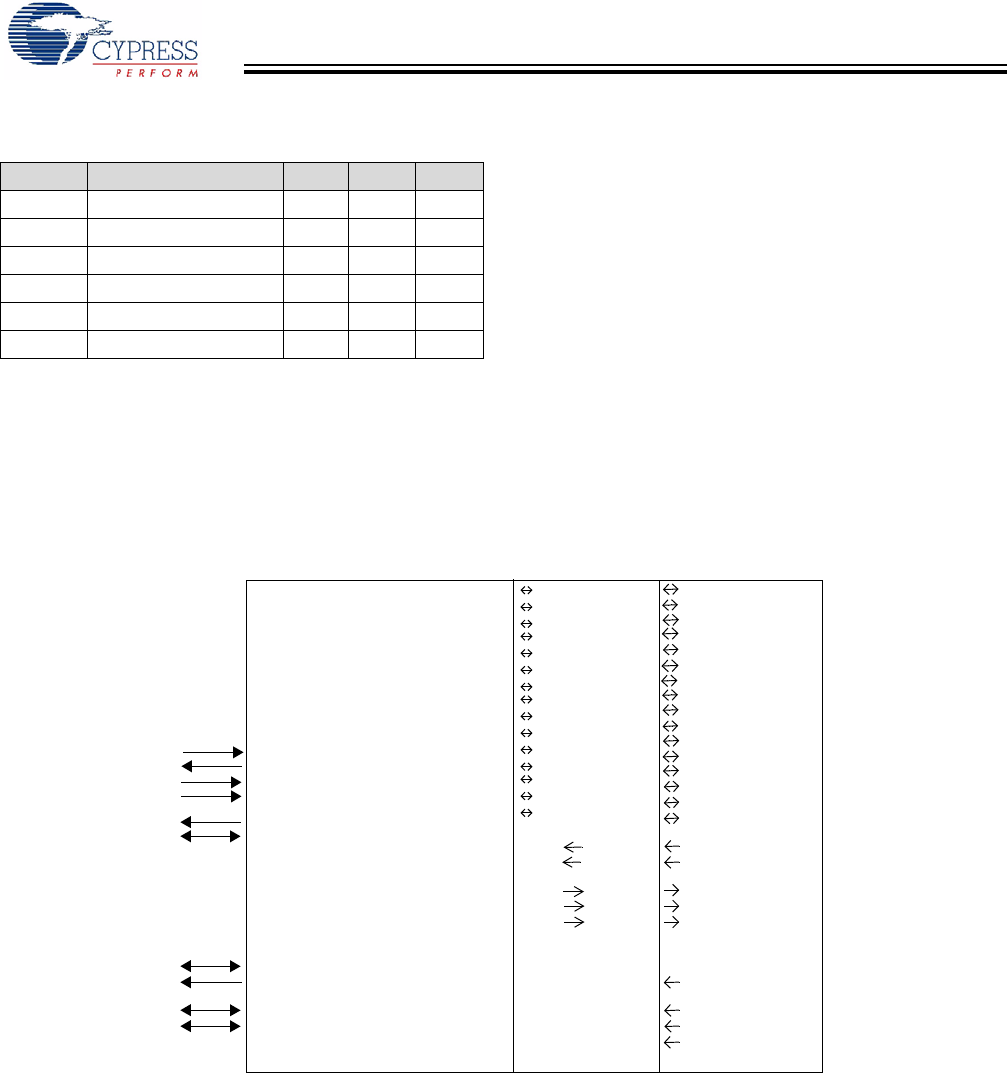
Figure 4-1 identifies all signals for the package. It is followed
by the pin diagram.Three modes are available: Port, GPIF
master, and Slave FIFO. These modes define the signals on
the right edge of the diagram. The 8051 selects the interface
mode using the IFCONFIG[1:0] register bits. Port mode is the
power on default configuration.
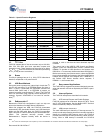
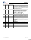
Table 3-6. Strap Boot EEPROM Address Lines to These
Values
Bytes Example EEPROM A2 A1 A0
16 24AA00
[8]
N/A N/A N/A
12824AA01 000
25624AA02 000
4K 24AA32 0 0 1
8K 24AA64 0 0 1
16K 24AA128 0 0 1
Note
8. This EEPROM does not have address pins.
XTALIN
XTALOUT
RESET#
WAKEUP#
SCL
SDA
IFCLK
CLKOUT
DPLUS
DMINUS
RDY0
RDY1
CTL0
CTL1
CTL2
INT0#/PA0
INT1#/PA1
PA2
WU2/PA3
PA4
PA5
PA6
PA7
FD[15]
FD[14]
FD[13]
FD[12]
FD[11]
FD[10]
FD[9]
FD[8]
FD[7]
FD[6]
FD[5]
FD[4]
FD[3]
FD[2]
FD[1]
FD[0]
SLRD
SLWR
FLAGA
FLAGB
FLAGC
INT0#/PA0
INT1#/PA1
SLOE
WU2/PA3
FIFOADR0
FIFOADR1
PKTEND
PA7/FLAGD/SLCS#
FD[15]
FD[14]
FD[13]
FD[12]
FD[11]
FD[10]
FD[9]
FD[8]
FD[7]
FD[6]
FD[5]
FD[4]
FD[3]
FD[2]
FD[1]
FD[0]
PD7
PD6
PD5
PD4
PD3
PD2
PD1
PD0
PB7
PB6
PB5
PB4
PB3
PB2
PB1
PB0
INT0#/PA0
INT1#/PA1
PA2
WU2/PA3
PA4
PA5
PA6
PA7
Port GPIF Master Slave FIFO
Figure 4-1. Signals
[+] Feedback


