


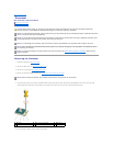
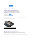


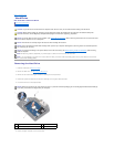
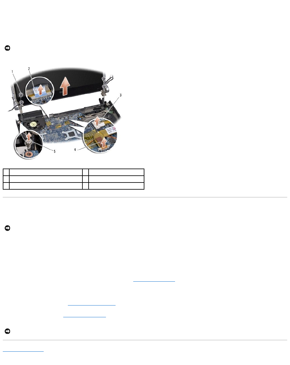
8. Disconnect the display cable, power light cable, and camera cable from their system board connectors and dislodge the cables from their routing guides.
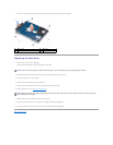
9. Remove the four screws (two on either side) that secure the display assembly to the computer base.
10. Lift the display assembly off the computer.
Replacing the Display Assembly
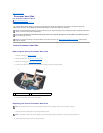
1. Place the display assembly in position and replace the four screws (two on either side) that secure the display assembly.
2. Replace the display cable grounding screw that secures the display ground cable to the system board.
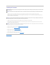
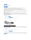
3. Carefully slide the Mini-Card antenna cables through the system board and into their routing guides.
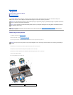
4. Reconnect the Mini-Card cables to the Mini-Card, if applicable (see Replacing the Mini-Card).
5. Route the power light cable and camera cable through the routing guides and connect the cables to the respective system board connectors.
6. Replace the optical drive (see Replacing the Optical Drive).
7. Replace the palm rest (see Replacing the Palm Rest).
Back to Contents Page
NOTICE: To avoid damage to the display, you must not disassemble your Edge-to- Edge display assembly.
1
screws (total 4; 2 on each side)
2
display cable pull-tab
3
power light cable connector
4
camera cable connector
5
display cable grounding screw
NOTICE: To avoid damage to the display, you must not disassemble your Edge-to- Edge display assembly.
NOTICE: Before turning on the computer, replace all screws and ensure that no stray screws remain inside the computer. Failure to do so may
result in damage to the computer.