


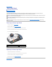


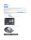
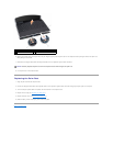

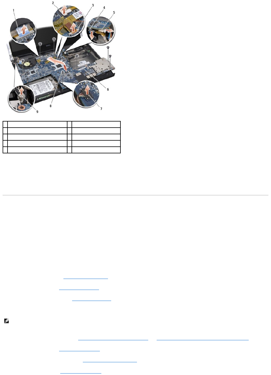
13. Disconnect the display cable, power light cable, camera cable, and status light board cable from the system board connector.
14. Lift the system board at an angle towards the side of the computer and disconnect the eSATA cable and AC adapter cable from the system board.
15. Lift the system board out of the computer base.
Replacing the System Board
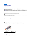
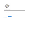
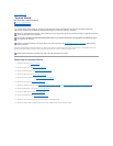
1. Place the system board in the computer base at an angle.
2. Connect the eSATA cable and the AC adapter cable to the system board and place the system board in position.
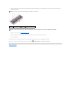
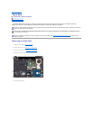
3. Replace the seven screws that secure the system board to the computer base.
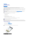
4. Connect the display cable, power light cable, camera cable, and status light board cable to the system board connector.
5. Replace the display cable grounding screw that secures the display ground cable to the system board.
6. Replace the optical drive (see Replacing the Optical Drive).
7. Replace the palm rest (see Replacing the Palm Rest).
8. Replace the Mini-Cards, if any (see Replacing the Mini-Card).
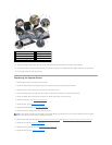
9. Place the new thermal cooling pads on the processor heat sinks.
10. Replace the processor heat sinks (see Replacing the Central Processor Heat Sink and Replacing the Graphic Processor Heat Sink/Thermal Fan).
11. Replace the rear caps (see Replacing the Rear Caps).
12. Replace the memory modules, if any (see Replacing the Memory Module(s)).
13. Replace the hard drive (see Replacing the Hard Drive).
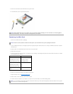
1
display cable pull-tab
2
power light cable connector
3
camera cable connector
4
eSATA cable connector
5
AC adapter cable connector
6
system board
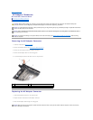
7
status light board cable connector
8
screws (7)
9
display cable grounding screw
NOTE: If the processor or system board is replaced, use the thermal cooling pad provided in the kit on the central processor heat sink and graphic
processor heat sink to ensure that thermal conductivity is achieved.