


1-8 Dell PowerEdge 4100/180 and 4100/200 Systems Service Manual
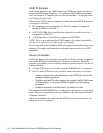
System Memory
The PowerEdge 4100 systems have a minimum of 64 MB of 72-bit-wide, buff-
ered EDO memory. The system memory capacity can be expanded to 1024 MB
(1 GB) by using combinations of 32- and 128-MB buffered, EDO dual in-line
memory modules (DIMMs) having gold connectors.
The system board has eight 168-pin DIMM sockets. The socket population rules
for the DIMMs are as follows:
• Populate the DIMM sockets in order from DIMM A (upper) to DIMM H
(lower).
• The DIMMs should be obtained from Dell to guarantee compatibility. All
system memory operates at the speed of the slowest DIMM installed.
• DIMMs of both capacities can be installed in the system. However, the
larger-capacity DIMMs should be installed in the top sockets, beginning
with socket DIMM A, with the smaller-capacity DIMMs installed after-
wards in order toward socket DIMM H.
The 72-bit wide, buffered EDO DIMMs support the ECC feature, which detects
memory errors and corrects single-bit memory errors. The ECC feature pro-
vides more reliable memory and less downtime, and is built into the memory
controller on the system board.
See “DIMMs” in Chapter 4 for information on removing and replacing DIMMs.
Advanced Expansion Subsystem
The computer system offers advanced expansion subsystems that can support a
mixture of traditional EISA expansion cards, Plug and Play ISA expansion cards,
and PCI expansion cards. The EISA Configuration Utility, included with the system,
provides a means of avoiding resource conflicts that might arise from such an
arrangement.
After all legacy cards have been configured with the EISA Configuration Utility,
the system automatically assigns required memory space, IRQ lines, and DMA
channels to any installed Plug and Play ISA expansion cards and PCI expansion
cards the next time the system is rebooted. Chapter 5, “Using the EISA Config-
uration Utility,” in the Dell PowerEdge 4100/180 and 4100/200 Systems User’s
Guide describes the EISA Configuration Utility and provides instructions for using it
to configure the system.
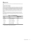
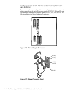
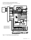
The eight expansion-card slots include three EISA expansion-card connectors
and five PCI expansion-card connectors. The expansion-card connectors are
located on the system board (see Figure 1-18).
Integrated Server Management
The system board contains integrated server management circuitry that moni-
tors critical system voltages and temperatures, as well as the operation and
speed of the system cooling fans. The integrated server management circuitry
works in conjunction with the Intel LANDesk
®
Server Management suite.