


1-12 Dell PowerEdge 4100/180 and 4100/200 Systems Service Manual
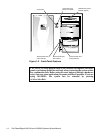
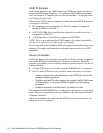
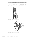
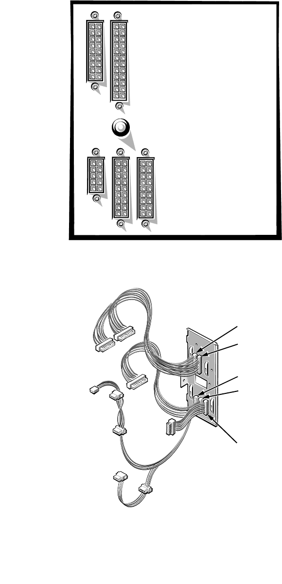
Pin Assignments for the DC Power Connectors (Nonredun-
dant Systems)
The power-supply output voltages for nonredundant systems can be measured
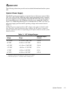
at the connectors on the back of the power supply (P1, P2, P3, P4, and P5) or at
the connectors on the power connector panel (J11, J12, J13, J14, and J15). The
following illustrations show both sets of connectors.
Figure 1-6. Power Supply Connectors
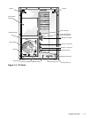
Figure 1-7. Power Connector Panel
P1
P2
P4
P3
P5
J11 (P1)
J12 (P2)
J13 (P3)
J14 (P4)
J15 (P5)