


1-18 Dell PowerEdge 4100/180 and 4100/200 Systems Service Manual
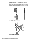
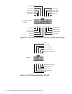
Figure 1-15. DC Power Connector PWRSCSI (DDBP)
1
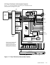
Wires 1 through 4 are connected to FD1 and FD2.
2
Wires 5 through 8 are connected to FD3 and FD4.
Figure 1-16. DC Power Connector PWRFD (FD1–FD4)
1 2 3 4 5 6 7
+5 VDC (red)
+12 VDC (yellow)
+5 VDC (red)
+12 VDC (yellow)
PWRSCSI
(DDBP)
8
9 10 11 12
13 14
common (black)
common (black)
common (black)
common (black)
common (black)
common (black)
+12 VDC (yellow)
+5 VDC (red)
+12 VDC (yellow)
common (black)
2 3
4
1
+5 VDC (red)
PWRFD
(FD1–FD4)
1
5 6 7
8
2
+12 VDC (yellow)
common (black)
common (black)
+12 VDC (yellow)
common (black)
common (black)
+5 VDC (red)