


System Overview 1-17
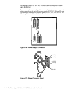
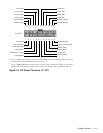
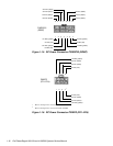
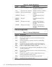
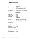
Figure 1-13. DC Power Connector PWR1
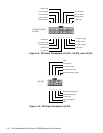
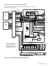
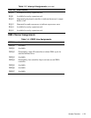
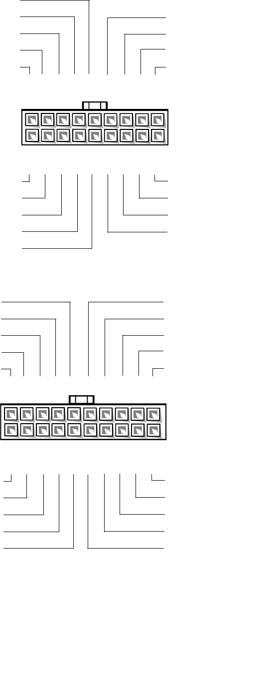
Figure 1-14. DC Power Connector PWR2 and PWR3
1 2 3 4 5 6 7
-12 VDC (blue)
PWR_STAT_BIT (gray)
-5 VDC (white)
8 9
NC_+12 sense
BAT_V (gray)
I
2
C_SDA (gray)
I
2
C_SCL (gray)
PRES_DET (gray)
+5 VDC sense (red)
PWR1
10
11 12 13 14
15 16
NC_NRLED
common (black)
POWER_GOOD (gray)
common (black)
NC_3INH
17 18
+5 VFP (violet)
+3.3 VDC sense (orange)
FAN_TACH (gray)
-3.3 VDC sense (black)
11
+5 VDC (red)
12 13 14 15 16
PWR2,
PWR3
common (black)
common (black)
1 2 3 4 5 9 10
+5 VDC (red)
+5 VDC (red)
6 7
8
common (black)
common (black)
common (black)
common (black)
17 18 19 20
+3.3 VDC (orange)
+3.3 VDC (orange)
+5 VDC (red)
+5 VDC (red)
common (black)
+12 VDC (yellow)
+12 VDC (yellow)
common (black)
+3.3 VDC (orange)
common (black)
common (black)