


Installing System Components 217
3
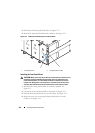
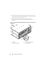
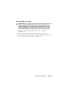
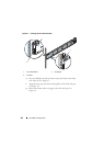
Connect the front panel board cable to the power management board and
secure the cable in the retaining clip. See Figure 3-18. For server enclosure
with external power source, see Figure 3-19.
4
Connect the fan cable to the power management board. See Figure 3-18.
For server enclosure with external power source, see Figure 3-19.
5
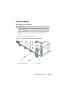
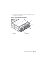
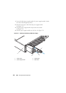
Slide the new fan bay cage into the enclosure until it is fully seated.
See Figure 3-17.
6
Secure the fan bay cage to the enclosure with the four screws.
See Figure 3-17.
7
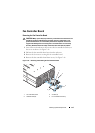
Reconnect the enclosure to its electrical outlet or PDU.
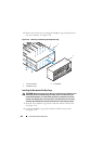
PDU Power Supply
The external PDU includes six power supply modules. All six power supply
modules must remain installed. Use the following procedure to remove and
replace a power supply module from the external PDU.
NOTE: The PDU device illustrations in this section is for reference only and may not
reflect the appearance of the actual device.
PDU Power Supply Indicator Code
The status indicator on the front of the power supply lights green to indicate
a valid power source is connected to the power supply and that power supply
is operational. An amber light indicates that a power supply failure event
occurred.
Removing a PDU Power Supply
CAUTION: Many repairs may only be done by a certified service technician. You
should only perform troubleshooting and simple repairs as authorized in your
product documentation, or as directed by the online or telephone service and
support team. Damage due to servicing that is not authorized is not covered by
warranty. Read and follow the safety instructions that came with the product.
CAUTION: To ensure proper airflow in the PDU, if a PSU module is removed it
should be immediately replaced with another module.
NOTE: The PDU power supply replacement procedure are provided as reference
only. See PDU device documentation for more information.