


16 Installation
www.dell.com | support.dell.com
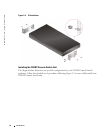
• Port Expansion Module (PEM)
• PS/2 Keyboard and Mouse Extension cable
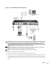
Verification of Ethernet/Computer Connections
The front panel of the 2161DS Console Switch features two LEDs describing the Ethernet
connection. The top LED is the
Link
indicator. It will illuminate when a valid connection to the
network is established and blink when there is activity on the port. The lower LED, labeled
100Mbps, will indicate that you are communicating at the 100Mb rate.
Additionally, there are two LEDs above each port number on the front of your unit: one green and
one amber. The green LED will illuminate when the SIP on that port is powered. The amber LED
will illuminate when that port is selected.
Setting Up Your Network
The 2161DS Console Switch system uses IP addresses to uniquely identify the 2161DS Console
Switch units, Avocent A1000R/A2000R units and the computers running Remote Console Switch
Software. The 2161DS Console Switch supports BootP (Bootstrap Protocol) and static IP
addressing. Dell recommends that IP addresses be reserved for each unit and that they remain
static while the 2161DS Console Switch units are connected to the network.
NOTE: Dell 2161DS Console Switch does not support dynamic IP address assignment or BootP
emulation through DHCP.
Rack Mounting Your 2161DS Console Switch
Obtain a Switch Mounting Bracket Kit (0U or 1U) to rack mount your 2161DS Console Switch
unit. Before installing the 2161DS Console Switch and other components in the rack, stabilize the
rack in a permanent location. Start rack mounting your equipment at the bottom of the rack, then
work to the top. Avoid uneven loading or overloading of racks.
CAUTION: Connect only to the power source specified on the unit. When multiple electrical
components are installed in a rack, ensure the total component power ratings do not exceed circuit
capabilities. Overloaded power sources and extension cords present fire and shock hazards.
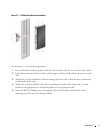
To install the 0U switch mounting bracket (shipped as default):
1
Line up the holes of the mounting brackets with the screw holes in the switch.
2
Fasten the mounting bracket to the switch using the button head socket cap screws on each
side.
3
Mount the switch assembly to the rack by inserting the three mounting hooks on one side of
the bracket into square holes in the vertical rack.
4
Press down until the blue push button pops out and clicks.