84 Configuring the I/O Modules
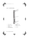
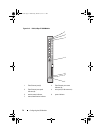
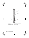
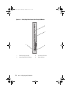
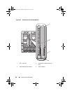
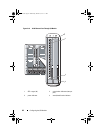
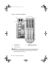
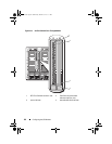
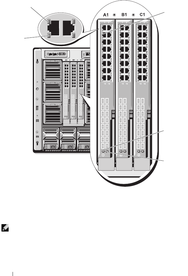
Figure 3-20. Ethernet Pass-Through Module
NOTE: Connectors on the Ethernet pass-through module correspond directly to the
blade number. For example, blade 5 is connected to port 5 on the Ethernet pass-
through module. Integrated network adapter 1 maps to I/O slot A1. Integrated
network adapter 2 maps to I/O slot A2.
1 link indicator (16) 2 RJ45 Ethernet connector (16)
3 power indicator 4 status/identification indicator
5 activity indicator (16)
1
5
2
3
4
book.book Page 84 Wednesday, March 9, 2011 3:11 PM


