


Ethernet Communication Module IFD9507
DVP-PLC Application Manual
10
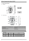
4 Registers in IFD9507
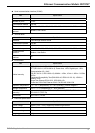
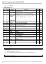
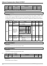
4.1 Basic Registers (BR)
BR#
Attribute
Content Explanation
Default Latched
0 R Model name
Set up by the system; read only. The model code of
IFD9507= H’0201
Yes
1 R Firmware version
Displaying the current firmware version in hex, e.g. V1.2 is
indicated as high byte = 0x01 and low byte = 0x20.
Yes
2 R
Release date of
the version
Displaying the date in decimal form. 10,000s digit and
1,000s digit are for “month”; 100s digit and 10s digit are for
“day”. For 1s digit: 0 = morning; 1 = afternoon.
Example: 12191 indicates the version released in the
afternoon of December 19.
Yes
3 Reserved
4 R/W
Communication
format
See the table of communication format setting No
5 R/W Baud rate See the table of baud rate setting No
6 R/W Address For setting up the station address No
7 R
Number of
DI/DO points
DI: high byte; DO: low byte 0x300 Yes
8 Reserved
9 R Error code Displaying the errors. See the table of error codes. 0 No
10 Reserved
11 R/W
Communication
time-out
For setting up the communication time-out (unit: ms) in
Modbus
5,000 Yes
12 R/W
Communication
delay time
For setting up the minimum interval time between every
communication datum
0 Yes
13 R/W Keep alive time
For setting up the communication time-out (unit: second) in
TCP connections
30 Yes
14 R/W I/O Enable Flag
High byte is input buffer enable flag. Low byte is output
buffer enable flag. The flag will be cleared when data was
sent.
0 No
15 R/W IP Index Destination IP index 1 Yes
16~32 Reserved
33 R/W
Returning to
default setting
0 No
Symbol “R” refers to read only; “R/W” refers to read and write.
4.2 Explanations on BR
BR#0: Model Name
Explanations:
1. Model code of IFD9507 = H'0201.
2. You can read the model code in the program to see if the extension module exists
BR#1: Firmware Version
Explanations:
The firmware version of IFD9507 is displayed in hex, e.g. H’0100 indicates version V1.00.